
ART
BEAUTY & WELLNESS
CRAFT
CULTURE & HISTORY
ENTERTAINMENT
ENVIRONMENT
FOOD & DRINKS
REVERSE ENGINEERING
SCIENCES
SPORTS
TECHNOLOGY
WEARABLES
Digital Spirit Level
Ed

Created by

Ed

14. August 2026FI
2
0
0
0
0

Digital Spirit Level

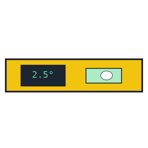
A level that reads tilt as a number instead of a bubble. The ADXL362 measures the constant one-g pull of gravity, and the angle of the board is recovered from how that one g divides between the axes. Because it measures gravity rather than a fluid, it can be zeroed against any surface you declare flat, and it reads two axes at once. The ADXL362 runs at 3.3 volts and its pins are not 5-volt tolerant, so a bi-directional level converter sits between it and the Arduino.
Intermediate
3 hours

Instructions

1

Solder headers to the accelerometer and level converter

Fit breakaway headers to both boards so they seat in the breadboard. Both are small-pitch parts — keep the iron brief so a pad does not lift.

Materials for this step:
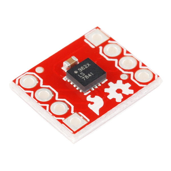
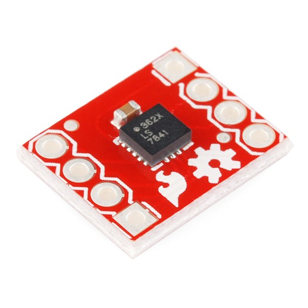
Triple Axis Accelerometer Breakout - ADXL362Triple Axis Accelerometer Breakout - ADXL3621 piece
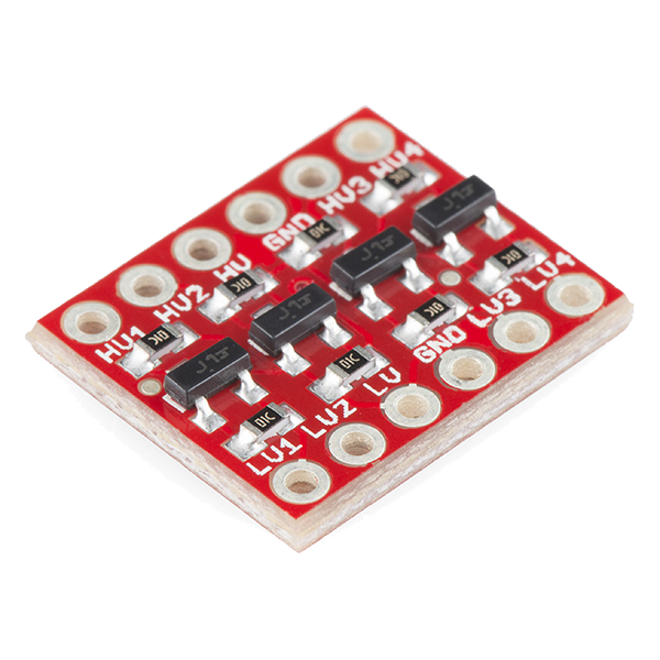
SparkFun Logic Level Converter - Bi-DirectionalSparkFun Logic Level Converter - Bi-Directional1 piece

Tools needed:

Ryobi ONE+ RSI18-0 Cordless Soldering IronRyobi ONE+ RSI18-0 Cordless Soldering Iron
2

Wire the accelerometer through the level converter — pin by pin

The converter has a low-voltage side (LV) and a high-voltage side (HV). The accelerometer is on LV, the Arduino on HV.

  1. Converter LV → Arduino 3.3V; converter HV → Arduino 5V; both GND rails common.
  2. ADXL362 VIN → Arduino 3.3V, ADXL362 GND → GND.
  3. ADXL362 SCLK → LV1 · HV1 → Arduino D13
  4. ADXL362 MOSI → LV2 · HV2 → Arduino D11
  5. ADXL362 MISO → LV3 · HV3 → Arduino D12
  6. ADXL362 CS → LV4 · HV4 → Arduino D10
Do not connect the ADXL362 to a 5 V pin at any point. Its supply maximum is 3.5 V and its inputs are not 5 V tolerant — one direct connection can end the part.

Materials for this step:

Arduino Uno R3 SMDArduino Uno R3 SMD1 piece
Breadboard - ClassicBreadboard - Classic1 piece
Jumper Wires Premium M/M 20 AWG - 15.5 cm (Pack of 10)Jumper Wires Premium M/M 20 AWG - 15.5 cm (Pack of 10)1 pack
3

Wire the display and set its contrast

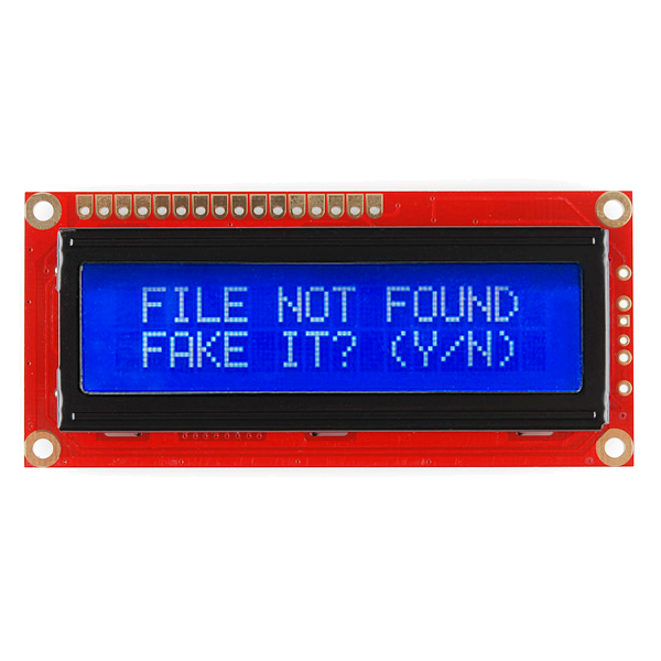
Wire the 16x2 display in 4-bit parallel mode. It is a 5 V part and connects straight to the Arduino — it does not go through the converter.

  1. LCD RSD7, ED6
  2. LCD D4 D5 D6 D7 → Arduino D5 D4 D3 D2
  3. LCD RW → GND, VSS → GND, VDD → 5V
  4. A 10 kΩ potentiometer across 5V and GND, wiper → LCD V0
A correctly wired display left at zero contrast shows a blank screen or a row of solid blocks, and reads exactly like a dead board. Set the contrast before debugging anything else.

Materials for this step:

Basic 16x2 Character LCD - 5VBasic 16x2 Character LCD - 5V1 piece
Resistor Kit - 1/4W (500 total)Resistor Kit - 1/4W (500 total)1 kit
USB-B CableUSB-B Cable1 piece
4

Upload the level sketch

Talks to the ADXL362 over raw SPI so every register write is visible rather than hidden in a library. SPI and LiquidCrystal ship with the IDE.

digital_spirit_level.inoarduino
// Digital Spirit Level
// ADXL362 (SPI, 3.3V, via level converter, CS on D10) + 16x2 LCD
//
// Gravity is a constant 1 g downward. How that 1 g divides between the
// axes gives the tilt, so the angle comes from atan2 of one axis against
// the other two -- no fluid, no bubble, and it can be re-zeroed anywhere.

#include <SPI.h>
#include <LiquidCrystal.h>

const int CS_PIN = 10;

// ADXL362 SPI instruction bytes
const byte CMD_WRITE_REG = 0x0A;
const byte CMD_READ_REG  = 0x0B;

// ADXL362 registers
const byte REG_XDATA_L   = 0x0E;   // X low; Y and Z follow consecutively
const byte REG_FILTER_CTL= 0x2C;
const byte REG_POWER_CTL = 0x2D;

LiquidCrystal lcd(7, 6, 5, 4, 3, 2);   // RS, E, D4, D5, D6, D7

float zeroPitch = 0.0, zeroRoll = 0.0;

void writeReg(byte reg, byte value) {
  digitalWrite(CS_PIN, LOW);
  SPI.transfer(CMD_WRITE_REG);
  SPI.transfer(reg);
  SPI.transfer(value);
  digitalWrite(CS_PIN, HIGH);
}

// Burst-reads X, Y, Z as three consecutive 12-bit signed values.
void readXYZ(int &x, int &y, int &z) {
  digitalWrite(CS_PIN, LOW);
  SPI.transfer(CMD_READ_REG);
  SPI.transfer(REG_XDATA_L);
  byte xl = SPI.transfer(0x00), xh = SPI.transfer(0x00);
  byte yl = SPI.transfer(0x00), yh = SPI.transfer(0x00);
  byte zl = SPI.transfer(0x00), zh = SPI.transfer(0x00);
  digitalWrite(CS_PIN, HIGH);

  x = (int)((xh << 8) | xl);
  y = (int)((yh << 8) | yl);
  z = (int)((zh << 8) | zl);

  // 12-bit two's complement sign-extended into 16 bits
  if (x > 2047) x -= 4096;
  if (y > 2047) y -= 4096;
  if (z > 2047) z -= 4096;
}

void readAngles(float &pitch, float &roll) {
  int x, y, z;
  readXYZ(x, y, z);
  pitch = atan2((float)x, sqrt((float)y * y + (float)z * z)) * 180.0 / PI;
  roll  = atan2((float)y, sqrt((float)x * x + (float)z * z)) * 180.0 / PI;
}

void setup() {
  Serial.begin(9600);
  pinMode(CS_PIN, OUTPUT);
  digitalWrite(CS_PIN, HIGH);

  SPI.begin();
  SPI.setDataMode(SPI_MODE0);
  SPI.setBitOrder(MSBFIRST);

  lcd.begin(16, 2);
  lcd.print(F("Digital Level"));

  delay(10);
  writeReg(REG_FILTER_CTL, 0x13);  // +/-2 g range, 100 Hz output data rate
  writeReg(REG_POWER_CTL,  0x02);  // measurement mode (0x00 would be standby)
  delay(100);

  // Whatever it is sitting on at power-up becomes 'flat'.
  readAngles(zeroPitch, zeroRoll);
  lcd.clear();
}

void loop() {
  float pitch, roll;
  readAngles(pitch, roll);
  pitch -= zeroPitch;
  roll  -= zeroRoll;

  lcd.setCursor(0, 0);
  lcd.print(F("Pitch "));
  lcd.print(pitch, 1);
  lcd.print(F("\xDF   "));   // degree symbol in the HD44780 character set

  lcd.setCursor(0, 1);
  lcd.print(F("Roll  "));
  lcd.print(roll, 1);
  lcd.print(F("\xDF   "));

  Serial.print(pitch, 2); Serial.print(F(",")); Serial.println(roll, 2);
  delay(200);
}
5

Zero it, then prove it with the reversal test

Lay the board on a surface you are treating as flat. It zeroes itself at power-up, so it will read close to 0.0.

  1. Turn the board end for end on the same surface.
  2. A correctly zeroed level now reads the same magnitude with the opposite sign.
If it does not reverse cleanly, the offset is wrong — or the surface is not as flat as you assumed. This test separates the two, which no single reading can do.

CC0 Public Domain

This blueprint is released under CC0. You are free to copy, modify, distribute, and use this work for any purpose, without asking permission.

Support the Maker by purchasing products through their Blueprint where they earn a Maker Commission set by Vendors, or create a new iteration of this Blueprint and include it as a connection in your own Blueprint to share revenue.

Discussion

(0)

Log in to join the discussion

Loading comments...