ART
BEAUTY & WELLNESS
CRAFT
CULTURE & HISTORY
ENTERTAINMENT
ENVIRONMENT
FOOD & DRINKS
REVERSE ENGINEERING
SCIENCES
SPORTS
TECHNOLOGY
WEARABLES
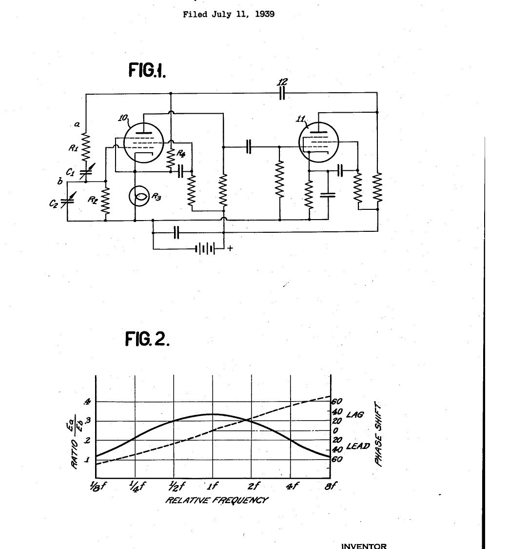


Function Generator: Resistance-Capacity Tuned Audio Oscillator with Lamp Amplitude Control (Hewlett, US 2,268,872, 1942)
The first Hewlett-Packard product: a test oscillator tuned by resistors and capacitors instead of coils. Two valve amplifiers feed their output back to their input through a series and a parallel R-C pair, which passes only one frequency in phase, so the circuit oscillates there. A second, negative feedback path through a small lamp holds the amplitude steady: as the swing grows the lamp warms, its resistance rises and the gain falls. One dial covers ten to one in frequency.
Result: a sine-wave signal generator covering 20 to 20,000 cycles in three ranges, about 0.25 % distortion.
Source: W. R. Hewlett, US 2,268,872 (1942). Unknown: valve types and component values. Picture: the patent drawing.
Advanced
Unknown
Instructions
1
1
Build the two-stage amplifier
Build the two-stage amplifier
Wire two amplifying valves in cascade with resistance-capacity coupling, the first's anode to the second's grid, run as class A amplifiers. Not given: valve types, values, the supplies. Ours: pentode valves in sockets.
Materials for this step:
 Pentode Valve2 pieces
 Valve Socket2 pieces
 Resistor1 set
 Capacitor Kit1 coupling and by-pass
 Aluminium Enclosure Box1 case
 Solder Wire1 as needed
Tools needed:
 Soldering Iron
2
2
Fit the tuning network
Fit the tuning network
From the second valve's anode, through a coupling capacitor, feed back to the first valve's grid through a resistor R1 in series with a variable capacitor C1, with a resistor R2 and variable capacitor C2 from the grid to ground. Make R1 = R2 and C1 = C2: the frequency is then 1/(2 pi R C), set by the capacitors, giving 10 to 1 on one dial. For the capacitors use a four-gang tuning capacitor with its sections paired in parallel. Switch three sets of resistors in for the ranges 20-200, 200-2000 and 2000-20,000 cycles. Ours: a rotary switch.
Materials for this step:
 Variable Capacitor (Air Dielectric)1 four-gangResistor1 three sets of R1, R2
 Rotary Switch1 range switch
Tools needed:
Soldering Iron Screwdriver Set
3
3
Fit the lamp feedback and use it
Fit the lamp feedback and use it
From the same output, through the coupling capacitor, feed back to the first valve's cathode across a resistor R4 and a small incandescent lamp R3. As the oscillation grows, the lamp heats, its resistance rises, the negative feedback increases and the gain falls, so the amplitude settles below the point of grid current with no clipping. The negative feedback also steadies the gain against valve and supply changes. Take the output from the terminals; Hewlett's test unit held its output within about 10 % over 20-20,000 cycles, with about 0.25 % distortion and under 0.1 % frequency shift with supply changes.
Materials for this step:
 Light Bulb1 small incandescent lampResistor1 R4
 Binding Post2 output
Tools needed:
 DC Power SupplySoldering Iron
Materials
10- 2 piecesPlaceholder
- 2 piecesPlaceholder
- 1 R4Placeholder
- 1 coupling and by-passPlaceholder
- 1 casePlaceholder
- 1 as neededPlaceholder
- 1 four-gangPlaceholder
- 1 range switchPlaceholder
- 1 small incandescent lampPlaceholder
- Placeholder
Tools Required
3- 2 vendors sell this, none ship to you yetPlaceholder
- Placeholder
- Placeholder
This blueprint makes

CC0 Public Domain
This blueprint is released under CC0. You are free to copy, modify, distribute, and use this work for any purpose, without asking permission.
Support the Maker by purchasing products through their Blueprint where they earn a Maker Commission set by Vendors, or create a new iteration of this Blueprint and include it as a connection in your own Blueprint to share revenue.