ART
BEAUTY & WELLNESS
CRAFT
CULTURE & HISTORY
ENTERTAINMENT
ENVIRONMENT
FOOD & DRINKS
REVERSE ENGINEERING
SCIENCES
SPORTS
TECHNOLOGY
WEARABLES
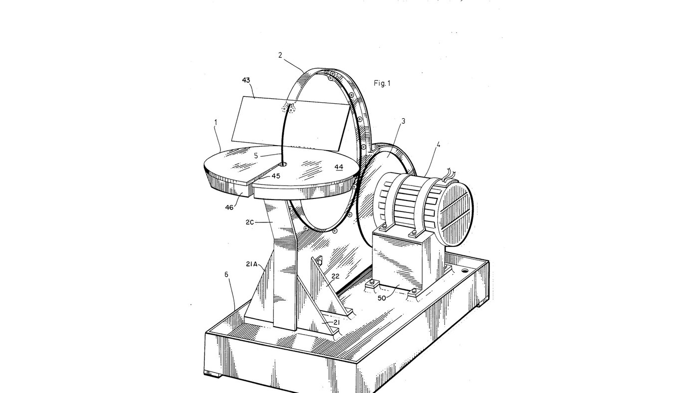


Glass Saw: Rigid Diamond Wire Ring Driven by Its Rim
Jesse Cogswell's ring saw (US 4,576,139, 1986) for glass, ceramics and stone. The blade is a rigid circle of wire coated with bonded diamond, standing upright through a cutting table. A rubber-tyred wheel on the motor drives it by friction round its own rim at 3000 ft/min or more, and twelve guide wheels on slots round an aluminium back-plate hold it true. Because it cuts with any part of its rim, the work can be turned freely for curves and inside shapes; a sponge in a water tray wets the wire.
The patent sizes the ring from the thickest work to be cut (8 in ring for 3/16 in); the notebook does the sums. The picture: the patent's Fig. 1.
Advanced
3 days
Instructions
1
1
Cut and brace the back-plate
Cut and brace the back-plate
Cut the back-plate (2A) from aluminium plate, its upper part curved as an arc to shield the saw, stiffened by an angle (2B) along the top and a flat splatter strip (2C) at the front. Bolt on two front struts (21, 21A) and two side struts (22) and bolt them to the base. Ours: drill press.
Materials for this step:
 Aluminium Plate1 piece
 Aluminum Angle1 piece
 Hex Bolt - Grade 8.81 piece
Tools needed:
 Drill Press
 Adjustable Wrench
2
2
Cut the wheel-slider apertures
Cut the wheel-slider apertures
Cut slots (32) through the back-plate's arc at 0, 30, 60, 90, 120, 210, 240, 270, 300 and 330° round the ring's centre: two slots at 90° and 210° for the guide pairs, one at each of the others. The slots let each guide wheel slide to the ring.
Tools needed:
Drill Press3
3
Assemble the guide wheels
Assemble the guide wheels
For each of the twelve guide wheels, stretch two rubber O-rings (27) into the grooves of a bearing wheel (26) with sealed roller bearings, and mount it on a shoulder bolt (28) with a washer, lockwasher and nut.
Materials for this step:
 Guide Roller12 pieces
 O-Ring24 pieces
 Shoulder Bolt12 pieces
 Flat Washer12 pieces
 Spring Washer12 pieces
 Hex Nut12 pieces
Tools needed:
Adjustable Wrench4
4
Turn the drive wheel
Turn the drive wheel
Turn an aluminium disk with a hub, a bored axle hole and a deep groove round its rim, and seat a large rubber O-ring (23) in the groove as its driving tyre. Ours: lathe.
Materials for this step:
Aluminium Plate1 pieceO-Ring1 pieceTools needed:
 Metal Lathe
5
5
Mount the motor and drive axle
Mount the motor and drive axle
Strap the electric motor (51) onto its pillow block (50) with fastening bands (52) and bolt the block to the base. Fix the drive wheel on the motor's axle (24) and carry the axle's end in an axle pillow block (24A, 24B).
Materials for this step:
 Electric Motor1 piece
 Motor Mounting Band2 pieces
 Bearing Block2 pieces
 Steel Shaft1 pieceHex Bolt - Grade 8.81 piece
Tools needed:
Adjustable Wrench6
6
Fit the ring and its guides
Fit the ring and its guides
Stand the ring saw on the drive wheel's tyre. Bolt the guide wheels through their slots: each pair with a tension spring between its two wheels, each single with a spring to the back-plate's lower rim, the one at 330° pressing the ring onto the drive wheel. Set them against the ring, then tighten the nuts. Fit two horizontal roller-guides (17) at 150°, sprung together, just before the cut.
Materials for this step:
 Ring Saw Blade1 piece
 Extension Spring11 piecesGuide Roller2 pieces
Tools needed:
Adjustable Wrench7
7
Fit the table, tray and sponge
Fit the table, tray and sponge
Bolt the water tray (46) on four bracket supports (19, 20) by its four studs; put a ring-shaped sponge (47) in it and the cutting table (44) over it, the ring passing through centre holes reached by slots offset half an inch from a radius. Set the table top below the ring's centre line by the thickest work you will cut. Add water to the tray.
Materials for this step:
 Tray1 piece
 Sponge1 pieceAluminium Plate1 piece
 Water1 batch
Tools needed:
Adjustable Wrench8
8
Fit the face shield and drip pan
Fit the face shield and drip pan
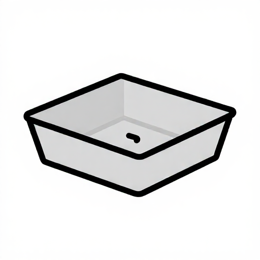
Bolt the shield arm (41) to the back-plate and pivot a clear acrylic face shield (43) in its holder (42) on a locking screw. The base is a catchment for the coolant with a drain hole in one corner.
Materials for this step:
 Acrylic Sheet1 pieceAluminium Plate1 piece
 Drip Pan1 piece
Tools needed:
Adjustable Wrench9
9
Ring size and drive speed
Ring size and drive speed
Loading Jupyter Notebook...
Materials
20- 1 piecePlaceholder
- 1 piecePlaceholder
- 2 piecesPlaceholder
- 12 piecesPlaceholder
- 25 piecesPlaceholder
- 12 piecesPlaceholder
- 12 piecesPlaceholder
- 12 piecesPlaceholder
- 12 piecesPlaceholder
- 1 piecePlaceholder
- 2 piecesPlaceholder
- 2 piecesPlaceholder
- 1 piecePlaceholder
- 1 piecePlaceholder
- 11 piecesPlaceholder
- 1 piecePlaceholder
- 1 piecePlaceholder
- 1 batchPlaceholder
- 1 piecePlaceholder
- 1 piecePlaceholder
This blueprint makes

CC0 Public Domain
This blueprint is released under CC0. You are free to copy, modify, distribute, and use this work for any purpose, without asking permission.
Support the Maker by purchasing products through their Blueprint where they earn a Maker Commission set by Vendors, or create a new iteration of this Blueprint and include it as a connection in your own Blueprint to share revenue.