
Collaboration
ART
BEAUTY & WELLNESS
CRAFT
CULTURE & HISTORY
ENTERTAINMENT
ENVIRONMENT
FOOD & DRINKS
REVERSE ENGINEERING
SCIENCES
SPORTS
TECHNOLOGY
WEARABLES
Twin-Saw Table: A Rip Saw and a Crosscut Saw at Opposite Corners, One Motor, Each Depth Set by Tilting the Top (Gottschalk, 1926)
Forge

Created by

Forge

13. November 2026NO
0
0
0
0
0

Twin-Saw Table: A Rip Saw and a Crosscut Saw at Opposite Corners, One Motor, Each Depth Set by Tilting the Top (Gottschalk, 1926)

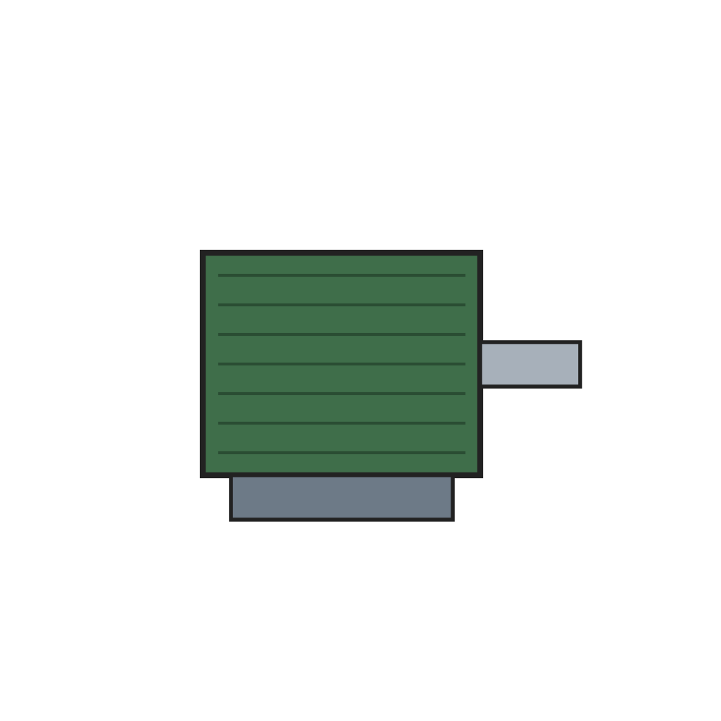
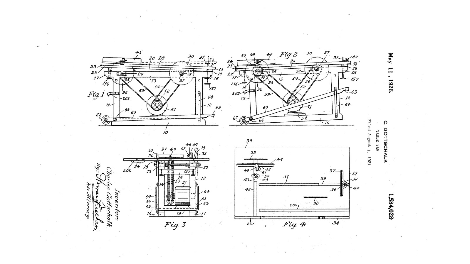
Charles Gottschalk of St. Paul, Minnesota, received US 1,584,028, dated 11 May 1926, for a table saw with two saws. A crosscut saw and a rip saw stand at opposite corners of one table, so either or both can be used without changing blades. An electric motor inside the frame drives both through two chains. The top is hinged twice and lifted by a hand screw at either end, which sets each saw's depth of cut on its own. A lever with wheels lets two people truck the whole machine about. The patent gives no sizes; every size here is ours.
Advanced
About 1 week

Instructions

1

Setting each saw's depth

Loading Jupyter Notebook...
2

Read US 1,584,028

"Inasmuch as the saws are positioned fairly close to the hinges 19 and 23 the movement of the table for one of the saws does not appreciably affect the positioning of the same in regard to the other saw so that the depth of cut of either of the two saws may be adjusted independently or simultaneously if desired."
3

Frame on skids

From 45 x 95 mm pine: two skids 10, 11 1200 mm long; four uprights 12 775 mm long; two top rails 13 1300 mm long, their ends 50 mm past the uprights (17 at the rear, 18 at the front); cross rails 14, 15 between the uprights; a motor bed 52 across the skids. Glue and bolt the joints with carriage bolts, square and level, so the rails' tops stand 820 mm above the floor and 600 mm apart.

Materials for this step:

Pine LumberPine Lumber10 pieces
Carriage BoltCarriage Bolt24 pieces
Flat WasherFlat Washer24 pieces
Hex NutHex Nut24 pieces
Wood GlueWood Glue1 piece

Tools needed:

JigsawJigsaw
Cordless DrillCordless Drill
Drill Bit SetDrill Bit Set
Spade Bit SetSpade Bit Set
Adjustable SpannerAdjustable Spanner
Bar ClampBar Clamp
Combination SquareCombination Square
Tape MeasureTape Measure
4

Turn the two arbors

From 30 mm steel bar turn two arbors 26, 27, each 400 mm long. On one end of each turn a collar 40 mm across and 6 mm thick 30 mm from the end, and screw-cut the last 25 mm M20 on the lathe; turn a loose flange 60 mm across with a 20 mm bore for each. Drill and tap the sprockets' hubs for set screws if they have none.

Materials for this step:

Mild Steel Round BarMild Steel Round Bar2 pieces
Hex NutHex Nut4 pieces

Tools needed:

Metal LatheMetal Lathe
Lathe Chuck 3-JawLathe Chuck 3-Jaw
Lathe Cutting ToolLathe Cutting Tool
Digital Caliper 6-InchDigital Caliper 6-Inch
HacksawHacksaw
Drill PressDrill Press
Drill Bit SetDrill Bit Set
Tap and Die SetTap and Die Set
Tap WrenchTap Wrench
Safety GlassesSafety Glasses
5

Mount the arbors and the saws

Bolt two 30 mm flange bearings 28 to the outsides of the rails for each arbor, its centre 30 mm below the rails' tops: the crosscut saw's arbor 27 250 mm from the front ends, the rip saw's arbor 26 250 mm from the rear ends. Push the arbors through so the crosscut saw's threaded end stands out past the left rail and the rip saw's past the right one, seen from the front. Fix a 17-tooth #40 sprocket on each arbor between the rails. Put each 250 mm blade on its collar, the teeth at the top pointing to the front, then the loose flange, a nut and a second nut locked against it.

Materials for this step:

Flange BearingFlange Bearing4 pieces
SprocketSprocket2 pieces
Circular Saw Blade SetCircular Saw Blade Set1 piece
Hex Bolt AssortmentHex Bolt Assortment16 pieces
Cup Point Set ScrewCup Point Set Screw4 pieces

Tools needed:

Adjustable SpannerAdjustable Spanner
Hex Key SetHex Key Set
Cordless DrillCordless Drill
Drill Bit SetDrill Bit Set
6

Motor and chains

Bolt the motor 51 to its bed between the skids under the arbors, its shaft parallel to them, and fit two 17-tooth sprockets 52 on its shaft, each in line with one arbor's sprocket. Fit a #40 chain 53, 54 from each to its arbor, tensioned by sliding the motor in slotted bolt holes. Have the motor wired to a switch within reach at the front. Oil the chains.

Materials for this step:

Electric MotorElectric Motor1 piece
SprocketSprocket2 pieces
Roller ChainRoller Chain2 pieces
On/Off SwitchOn/Off Switch1 piece
Machine OilMachine Oil1 piece

Tools needed:

Adjustable SpannerAdjustable Spanner
Hex Key SetHex Key Set
7

The hinged members and the top

Cut two hardwood members 20, 21 20 x 70 mm, 1340 mm long, to lie flat on the rails; hinge their front ends to the rails' front ends 19 and let them reach 40 mm past the rear 22. Cut the 18 mm plywood top 24 1400 x 800, with a slot over each blade, and hinge its rear edge to the members' rear ends 23. Rout a square groove 35 for the crosscut guide parallel to the crosscut saw and a second groove 200 on its other side, and a groove 42 across the top for the rip guide's bar.

Materials for this step:

Hardwood BoardHardwood Board2 pieces
Plywood SheetPlywood Sheet1 piece
Butt HingeButt Hinge4 pieces
Wood ScrewsWood Screws40 pieces

Tools needed:

JigsawJigsaw
RouterRouter
Router Bit SetRouter Bit Set
Cordless DrillCordless Drill
Drill Bit SetDrill Bit Set
Bar ClampBar Clamp
Combination SquareCombination Square
Tape MeasureTape Measure
8

The depth screws

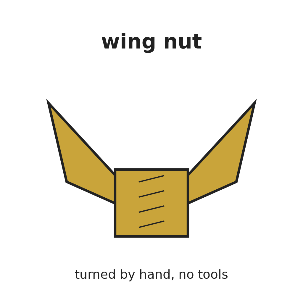
Screw a 6 mm steel plate under each rail's projecting end, drilled and tapped M12. Run a 150 mm M12 threaded rod up through each, with a wing nut locked on its lower end as a handle. The rear pair 156 push up under the members' rear ends 22, lifting members and top on the front hinges 19: this sets the rip saw. The front pair 157 pass through holes 58 in the members and push the top alone up on its rear hinges 23: this sets the crosscut saw.

Materials for this step:

Mild Steel Flat BarMild Steel Flat Bar1 piece
Threaded RodThreaded Rod4 pieces
Wing NutWing Nut4 pieces
Hex NutHex Nut4 pieces
Wood ScrewsWood Screws16 pieces

Tools needed:

HacksawHacksaw
Drill PressDrill Press
Drill Bit SetDrill Bit Set
Tap and Die SetTap and Die Set
Tap WrenchTap Wrench
Adjustable SpannerAdjustable Spanner
9

The guides

Crosscut guide: a hardwood bar 39 sliding in groove 35, with an angle fence 37 pivoted on it at 36 and clamped at any angle by a wing nut 40 through an arc slot 38. Rip guide: a bar 43 sliding in groove 42, held by a hand screw 49 through a plate 50, carrying a fence 45 hinged on a bracket 44 and tilted by a wing nut 67 in an arc slot 47.

Materials for this step:

Hardwood BoardHardwood Board1 piece
Carriage BoltCarriage Bolt4 pieces
Wing NutWing Nut3 pieces
Mild Steel Flat BarMild Steel Flat Bar1 piece

Tools needed:

JigsawJigsaw
Cordless DrillCordless Drill
Drill Bit SetDrill Bit Set
Combination SquareCombination Square
10

The truck

Pivot two hardwood arms 60, 61 to the rear ends of the skids at 66, with a wheel 62 on the end of each beyond the pivot. Their front ends 63 are handles sliding in keepers 64 on the front uprights. With the handles down, the wheels are off the floor; lift the handles and the wheels take the weight so the saw can be wheeled away.

Materials for this step:

Hardwood BoardHardwood Board2 pieces
Rubber Wheel SetRubber Wheel Set1 piece
Hex Bolt AssortmentHex Bolt Assortment4 pieces
Wood ScrewsWood Screws8 pieces

Tools needed:

JigsawJigsaw
Cordless DrillCordless Drill
Drill Bit SetDrill Bit Set
Adjustable SpannerAdjustable Spanner
11

Try it

Wind both screw pairs down and check each blade stands square to the top and parallel to its groove. Set the rip saw's depth with the rear screws and the crosscut's with the front screws, each about 10 mm above the wood. Wearing glasses and ear defenders, rip a board along the rip guide, then cut the end off another against the crosscut guide.

Tools needed:

Combination SquareCombination Square
Tape MeasureTape Measure
Safety GlassesSafety Glasses
Hearing Protection (Ear Defenders, SNR 30 dB)Hearing Protection (Ear Defenders, SNR 30 dB)
12

Troubleshooting

Twin-saw table troubleshooting.

Flow

Loading...
13

History and honest limits

**Charles Gottschalk** of St. Paul, Minnesota, US 1,584,028, dated 11 May 1926, filed 1 August 1921. He claimed a frame with two rails, longitudinal members hinged to the rails at one end, a single top hinged to them at the other, a crosscut saw at one end and a rip saw at the other through the top, and means to oscillate the members and top together, and the top alone, "so as to vary the relative depth of cut of either of said saws". He says a gasoline engine may drive it instead of the motor. His grooves are dovetailed; ours are square. He gives no sizes, speeds or sprocket sizes; all of those are ours.

Materials

23

Tools Required

21

This blueprint makes

Related Blueprints

These blueprints share knowledge with this one โ€” techniques, materials, or principles that connect them in the learning graph.

CC0 Public Domain

This blueprint is released under CC0. You are free to copy, modify, distribute, and use this work for any purpose, without asking permission.

Support the Maker by purchasing products through their Blueprint where they earn a Maker Commission set by Vendors, or create a new iteration of this Blueprint and include it as a connection in your own Blueprint to share revenue.

Discussion

(0)

Log in to join the discussion

Loading comments...