Collaboration
ART
BEAUTY & WELLNESS
CRAFT
CULTURE & HISTORY
ENTERTAINMENT
ENVIRONMENT
FOOD & DRINKS
REVERSE ENGINEERING
SCIENCES
SPORTS
TECHNOLOGY
WEARABLES
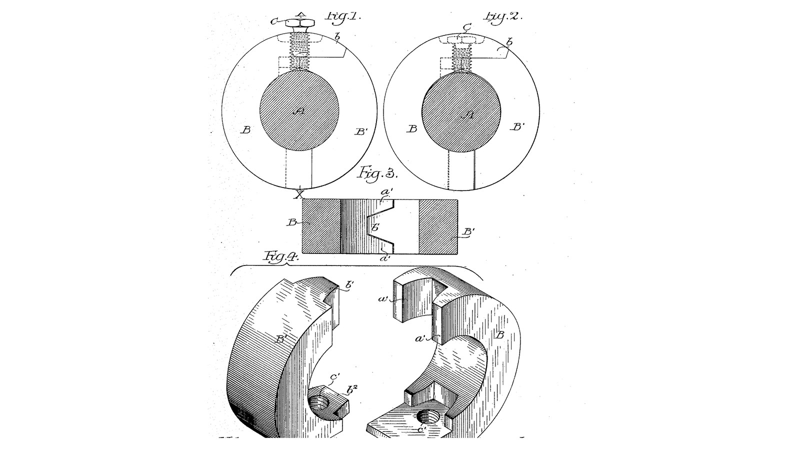


One-Screw Two-Part Shaft Collar: Hooked Ends Reach Round the Shaft So the Halves Cannot Open (Grundy, 1907)
John R. Grundy of Philadelphia received US 860,369, dated 16 July 1907, for a two-part collar held by a single screw, where earlier split collars needed two. The screw passes through one pair of ends, an overhang on one part lying over the other. At the opposite side a tongue on one part fits a recess in the other. Both of those ends reach round the shaft past the diameter under the screw. When the screw's point presses the shaft, they hook under it and cannot open. Each part goes onto the shaft from the side, so the shaft stays in its bearings.
We cut the two parts from a turned brass ring with a piercing saw, from a full-size template. The patent gives no sizes; every size here is ours.
Advanced
About 2 days
Instructions
1
1
Why the hooks hold
Why the hooks hold
Loading Jupyter Notebook...
2
2
Read US 860,369
Read US 860,369
"It is obvious that by using the single screw in place of a plurality of screws, as has hitherto been considered necessary, I am enabled to reduce the cost of the collar."
"The parts of said collar are placed in position on the shaft by being moved toward it in radial planes."
3
3
Turn the ring
Turn the ring
Grip 45 mm brass round bar in the 3-jaw chuck. Face it, turn it to 40 mm for 20 mm, centre-drill, drill through 15 mm and ream 16 mm. Part off 16 mm long and face the parted side.
Materials for this step:
 Brass Round Bar1 piece
Tools needed:
 Metal Lathe
 Lathe Chuck 3-Jaw
 Lathe Cutting Tool
 Center Drill Set
 Drill Bit Set
 Reamer
 Parting Tool
 Digital Caliper 6-Inch
 Safety Glasses
4
4
Print the cutting template
Print the cutting template
Full-size A4 template: the end view of the ring with the outlines of parts B and B', and the bottom of the ring seen from below with the tongue b' and cheeks a'. Print at 100 %; its 50 mm bar must measure 50 mm.
5
5
Cut the parts apart
Cut the parts apart
Glue the end view on one end face of the ring, centred, and the strip on the outside at the bottom. Wax the blade. Top joint: hold the ring in soft jaws, face up, and saw with the blade along the axis: in from the outside 5 mm left of the line to 14 mm radius, round the 14 mm circle to the line, and down the line into the bore. Bottom joint: turn the ring over and saw with the blade across the wall, following the strip from one end face to the other: the cheeks a' 3 mm left of the line, the tongue b' 3 mm right of it. Go slowly at the corners; the two parts come apart.
Tools needed:
 Inkjet Printer
 Glue
 Bench Vise
 Vice Soft Jaws
 Jeweler's Saw
 Beeswax
6
6
Fit the joints and cut away the bores
Fit the joints and cut away the bores
File the saw marks off the joints until the tongue slides into its recess and the overhang lies on the other part, with the two parts round a 16 mm bar. File each part's bore out to 18 mm across over the 22 degrees next to the top joint on its own side, B' to the left of the line and B to the right, as the template shows. Try them on the bar: put B on from below right, then B' from below left, sliding it up under the overhang and the tongue into its recess. File until each goes on without forcing.
Tools needed:
 Mild Steel Round BarBench ViseVice Soft Jaws
 File Set
 Needle File SetDigital Caliper 6-Inch
7
7
Drill and tap for the screw
Drill and tap for the screw
With both parts on the bar, the overhang lying on B', clamp the bar in the machine vice so the dashed screw line on the template stands upright. Drill 4.2 mm through the overhang and through B' into the bore, and tap M5 through both with cutting oil. Take the parts off and deburr the bore.
Materials for this step:
 Cutting Oil1 piece
Tools needed:
Mild Steel Round Bar Drill Press
 Machine ViceDrill Bit Set
 Tap and Die Set
 Tap Wrench
 Deburring Tool
8
8
The collar in 3D
The collar in 3D
FreeCAD model, our sizes: parts B and B' on a 16 mm shaft, the overhang b and the M5 screw at the top, the tongue b' between the cheeks a' at the bottom, and the bores cut away beside the top joint.
9
9
Fit it on the shaft
Fit it on the shaft
Run an M5 x 12 cup point set screw into the overhang until it just shows. Put B onto the shaft from the side where the collar is wanted, then B' from the other side, its top under the overhang and its tongue into the recess. Tighten the screw with the hex key: it pushes on the shaft and draws both bottom ends down against it. Try to slide and turn the collar; it must not move.
Materials for this step:
 Cup Point Set Screw1 piece
Tools needed:
 Hex Key Set
10
10
Troubleshooting
Troubleshooting
Grundy collar troubleshooting.
Flow
Loading...
11
11
History and honest limits
History and honest limits
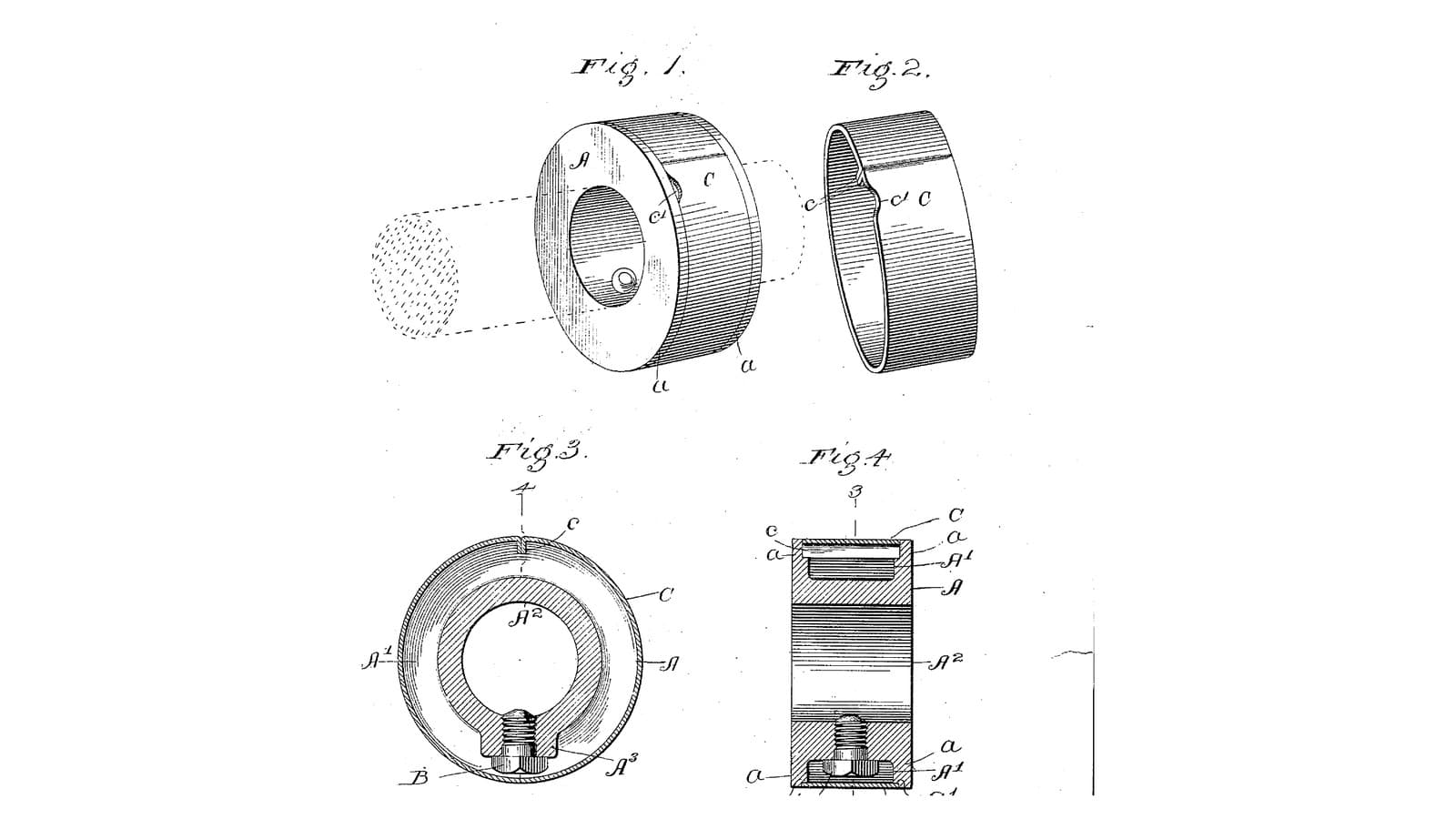
**John R. Grundy** of Philadelphia, US 860,369, dated 16 July 1907, filed 28 January 1907. He claimed "a shaft collar made in two parts, and means for holding the parts together comprising a single screw passing through two adjacent ends of said two parts, the other ends of said parts being formed to co-act with the shaft to prevent their separation". His screw end also has a second projection b2 in a recess, holding the parts in line along the shaft; ours leaves it out, as the screw through both parts does that. His screw has a hex head; ours is a socket set screw. He gives no material; ours is brass, which a piercing saw cuts well. The patent gives no sizes; every size here is ours.
Materials
3- 1 piecePlaceholder
- 1 piecePlaceholder
- 1 piecePlaceholder
Tools Required
24- Placeholder
- Placeholder
- Placeholder
- Placeholder
- Placeholder
- Placeholder
- Placeholder
- Placeholder
- Placeholder
- Placeholder
- Placeholder
- Placeholder
- Placeholder
- Placeholder
- Placeholder
- Placeholder
- Placeholder
- Placeholder
- Placeholder
- Placeholder
- Placeholder
- Placeholder
- Placeholder
- Placeholder
Design Files
2This blueprint makes
Related Blueprints
These blueprints share knowledge with this one — techniques, materials, or principles that connect them in the learning graph.
CC0 Public Domain
This blueprint is released under CC0. You are free to copy, modify, distribute, and use this work for any purpose, without asking permission.
Support the Maker by purchasing products through their Blueprint where they earn a Maker Commission set by Vendors, or create a new iteration of this Blueprint and include it as a connection in your own Blueprint to share revenue.