Collaboration
ART
BEAUTY & WELLNESS
CRAFT
CULTURE & HISTORY
ENTERTAINMENT
ENVIRONMENT
FOOD & DRINKS
REVERSE ENGINEERING
SCIENCES
SPORTS
TECHNOLOGY
WEARABLES
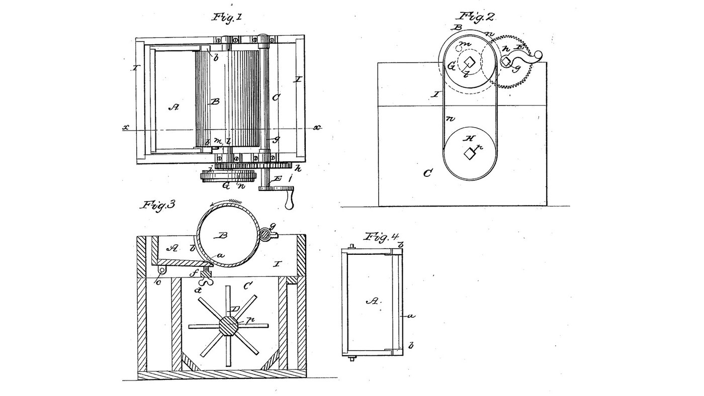

Hot-Water Cylinder Churn: Cream Is Crushed Between a Warm Turning Cylinder and an Adjustable Plate, Then Falls to a Dasher
Jason W. Hardie of New York received US 27,446, dated 13 March 1860, for a churn. Cream in a hopper is drawn between a turning cylinder filled with hot water and a plate set close against it, which crushes the butter globules and warms them only for that moment; it falls in a thin sheet into the churn body, losing the heat again, and a dasher driven by a band from the cylinder gathers the butter.
The patent gives no sizes and no water temperature; every size here is ours.
Advanced
About 3 days, plus printing
Instructions
1
1
Warm for a moment only
Warm for a moment only
Loading Jupyter Notebook...
2
2
A turning cylinder churn, one month before
A turning cylinder churn, one month before
Ward churns inside his cylinder. Hardie works the cream on the outside of his, against a plate.
3
3
Read US 27,446
Read US 27,446
"It is desirable to have the butter globules warmed only at the moment they are acted on, and to heat the milk or cream as little, and as little time, as possible, to make good butter." ... "And the cream, after passing under the cylinder, falls in a thin sheet, or in small streams, or drops, through the air, into the churn body beneath, thereby again parting with much of the heat acquired from the cylinder."
4
4
Print the cog-wheel h
Print the cog-wheel h
Spur gear, module 2.5, 60 teeth, 18 mm wide, with a hub 30 mm across; bored 16.4 mm. PETG, 0.2 mm layers, 40 % infill, 4 walls.
5
5
Print the pinion i
Print the pinion i
Spur pinion, module 2.5, 16 teeth, 18 mm wide, with a hub 30 mm across; bored 16.4 mm. PETG, 0.2 mm layers, 40 % infill, 4 walls.
6
6
Print the pulleys G and H
Print the pulleys G and H
Pulley 100 mm across with a round groove for an 8 mm belt; bored 16.4 mm. Print two. PETG, 0.2 mm layers, 40 % infill, 4 walls.
7
7
Churn body C and frame I
Churn body C and frame I
From 20 mm hardwood board make the body 400 x 350 mm inside and 350 deep; glue and screw it and seal the inside joints with silicone sealant. Bore the two long walls 16.8 mm across, 120 mm above the floor and on the centre line, for the dasher's shaft p. For the frame I cut two cheeks 440 x 230 mm that stand on the body's long walls, joined by cleats so the frame lifts off. Bore both cheeks 16.8 mm for the cylinder's shaft l, 40 mm from the centre and 120 mm above the body's top edge, and 16.8 mm for the winch shaft g, 95 mm from l at 45 degrees up and outward. Screw a hardwood cross-piece f, 40 x 20 mm, between the cheeks under the plate's place, and fit a nut in it for the thumb-screw d.
Materials for this step:
 Hardwood Board4 pieces
 Wood Glue1 piece
 Wood Screws40 pieces
 Silicone Sealant1 piece
 Hex Nut1 piece
Tools needed:
 Table Saw
 Jigsaw
 Cordless Drill
 Drill Bit Set
 Bar Clamp
 Screwdriver Set
 Tape Measure
 Sandpaper
8
8
Cylinder B, shaft l and stopper m
Cylinder B, shaft l and stopper m
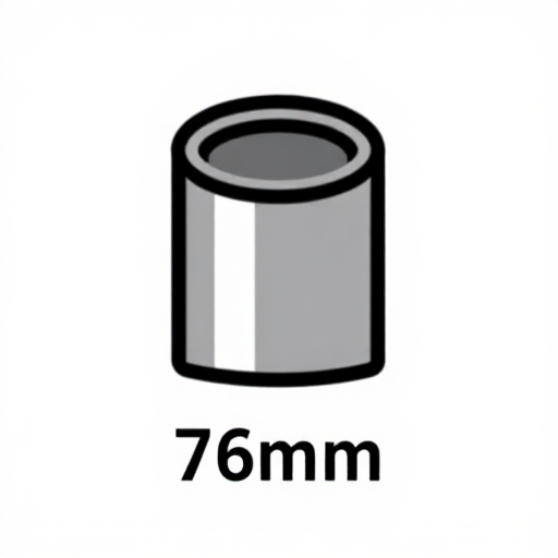
Cut 300 mm of stainless tube 160 mm across. Cut two end discs from 15 mm HDPE sheet to fit inside it; bore both 16 mm on the centre for a 16 mm stainless shaft, 500 mm long, and one 20 mm, 50 mm off centre, for a rubber stopper. Press the discs into the tube on the shaft, screw them through the tube with stainless screws, and seal the discs and the shaft's passage with silicone sealant so the cylinder holds water.
Materials for this step:
 Stainless Steel Tube1 piece
 HDPE Sheet1 piece
 Stainless Steel Rod1 piece
 Rubber Stoppers1 piece
 Machine Screws12 piecesSilicone Sealant1 piece
Tools needed:
 HacksawJigsawCordless DrillDrill Bit Set
 Files (Hand File)Screwdriver Set
9
9
Hopper A, plate a, packing strips b and thumb-screw d
Hopper A, plate a, packing strips b and thumb-screw d
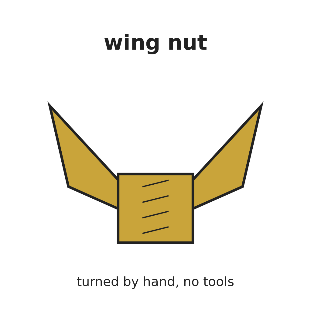
Make a hardwood hopper 302 mm long inside, to take the cylinder: an outer wall, two end walls and a bottom sloping down to the cylinder, its inner edge cut to the cylinder's curve. Bend a strip of stainless sheet to the curve and screw it over that edge as the plate a. Screw HDPE strips on the end walls' inner faces as packing b, to run against the cylinder's ends. Hang the hopper's outer bottom corner on a 10 mm stainless pin c through the cheeks. Cut 60 mm of threaded rod with a wing nut locked on one end as the thumb-screw d; run it up through the cross-piece's nut to bear under the hopper, and turn it until the plate is about 1.5 mm from the cylinder.
Materials for this step:
Hardwood Board1 piece Stainless Steel Sheet1 pieceHDPE Sheet1 pieceStainless Steel Rod1 piece
 Threaded Rod1 piece
 Wing Nut1 pieceHex Nut1 pieceWood Screws16 piecesWood Glue1 piece
Tools needed:
Table SawJigsaw Tin Snips
 Bench ViseCordless DrillDrill Bit SetHacksaw
 Adjustable SpannerScrewdriver Set
10
10
Dasher D, gears, winch E and band n
Dasher D, gears, winch E and band n
Pass a 16 mm stainless shaft p through the body's walls and fit the dasher on it: a hardwood hub with eight 12 mm dowel arms reaching 100 mm, in three sets along the shaft. Fit the cylinder's shaft in the cheeks with the pinion i on one end and the pulley G on the other, the cog-wheel h on the winch shaft g meshing the pinion, and a hardwood crank with a dowel handle on g as the winch E. Fit the pulley H on the dasher shaft's end, under G, and join them with a round belt. Hold every shaft with collars.
Materials for this step:
Stainless Steel Rod2 piecesHardwood Board1 piece Hardwood Dowels2 piecesWood Glue1 piece
 PETG Filament1 piece
 Drive Belt1 piece
 Shaft Collar6 pieces
 Split Pin2 pieces
Tools needed:
 FDM 3D PrinterHacksawFiles (Hand File)Cordless DrillDrill Bit SetBench ViseAdjustable Spanner
11
11
The build in 3D
The build in 3D
FreeCAD model of this build, partly cut away: the body C with the dasher D, the frame I, the cylinder B on its shaft with the pinion i and cog-wheel h on the winch shaft, the hopper A with its plate a against the cylinder, the pivot c and thumb-screw d, and the band n from pulley G to pulley H.
12
12
Churn
Churn
Fill the cylinder with warm water from the kettle through the stopper's hole and close it; the patent gives no temperature, so check it with the thermometer and note it with the time the butter takes. Pour about 6 litres of heavy cream at about 15 °C into the hopper and turn the winch steadily, timing it; add cream to the hopper as it runs through. When the butter has gathered on the dasher, lift off the frame, take out the butter, tip the buttermilk into a bowl, wash the butter in cold water until it runs clear, salt and weigh it.
Materials for this step:
 Heavy Cream6 l
 Water1 piece
 Coarse Sea Salt1 piece
Tools needed:
 Electric Kettle
 Leave-In Probe Thermometer
 Stopwatch
 Digital Kitchen Scale
 Stainless Steel Mixing Bowl (Large)
13
13
Troubleshooting
Troubleshooting
Hot-water cylinder churn troubleshooting.
Flow
Loading...
14
14
History and honest limits
History and honest limits
**Jason W. Hardie** of New York, US 27,446, 13 March 1860 (signed 25 October 1859), "Churn". He disclaimed cylinders working against each other, plane rubbing surfaces, and hot water in the dasher or the main body of cream, and claimed the hollow revolving cylinder with hot water and an adjustable fixed surface against it. He gives no water temperature and no sizes; every size here is ours, our gears and pulleys are printed and sit on opposite ends of the cylinder, where his are on one end.
Materials
21- 4 piecesPlaceholder
- 3 piecesPlaceholder
- 56 piecesPlaceholder
- 2 piecesPlaceholder
- 2 piecesPlaceholder
- 1 piecePlaceholder
- 1 piecePlaceholder
- 2 piecesPlaceholder
- 1 piecePlaceholder
- 12 piecesPlaceholder
- 1 piecePlaceholder
- 1 piecePlaceholder
- 1 piecePlaceholder
- 2 piecesPlaceholder
- 1 piecePlaceholder
- 1 piecePlaceholder
- 6 piecesPlaceholder
- 2 piecesPlaceholder
- 6 lPlaceholder
- 1 piecePlaceholder
- 1 piecePlaceholder
Tools Required
19- 1 vendor sell this, none ship to you yetPlaceholder
- 1 vendor sell this, none ship to you yetPlaceholder
- 1 vendor sell this, none ship to you yetPlaceholder
- Placeholder
- Placeholder
- Placeholder
- 1 vendor sell this, none ship to you yetPlaceholder
- Placeholder
- Placeholder
- Placeholder
- Placeholder
- Placeholder
- Placeholder
- Placeholder
- Placeholder
- Placeholder
- Placeholder
- Placeholder
- Placeholder
Design Files
4This blueprint makes


Related Blueprints
These blueprints share knowledge with this one — techniques, materials, or principles that connect them in the learning graph.
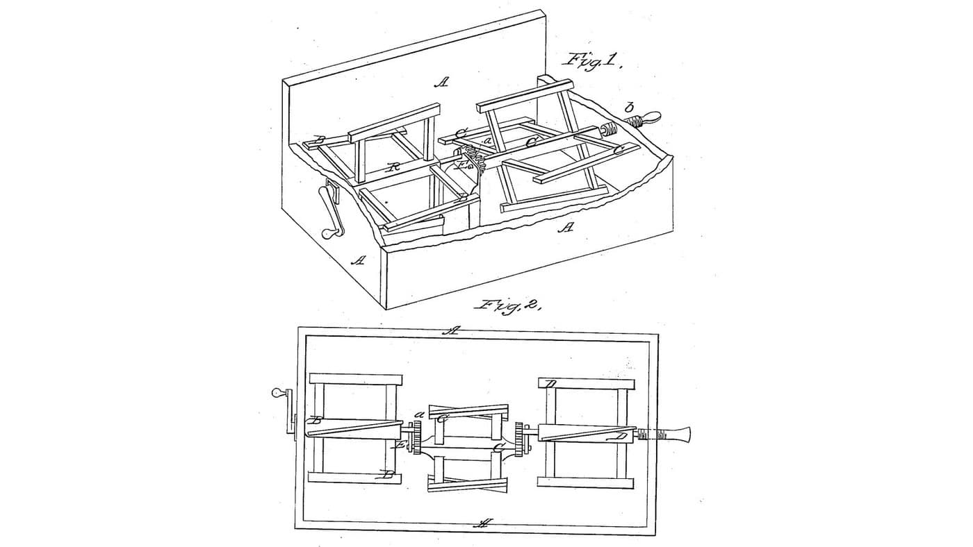
Counter-Revolving Dasher Churn: Geared Dashers on Offset Shafts Turn Contrary Ways, Their Blades Skewed Contrary Ways
by Buttercup
Woodworking
0
0
0
0
0
0
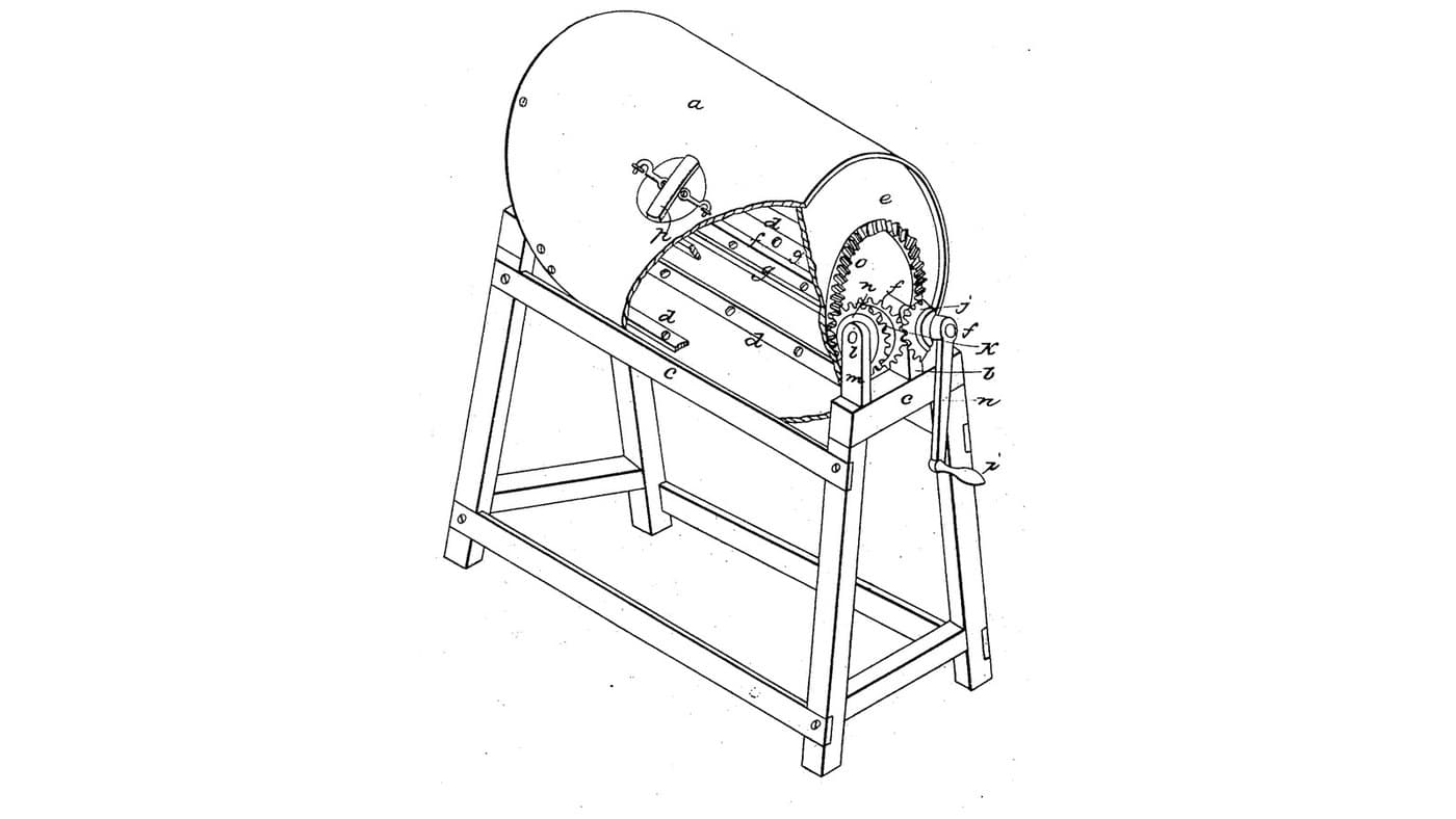
Counter-Turning Cylinder Churn: The Ribbed Cylinder Turns One Way While the Dashers Inside Turn the Other
by Buttercup
Woodworking
0
0
0
0
0
0

Churning Butter from Cream — The 5,000-Year-Old Fat Separation
by TheChef
CRAFT
60
0
0
0
0
0
CC0 Public Domain
This blueprint is released under CC0. You are free to copy, modify, distribute, and use this work for any purpose, without asking permission.
Support the Maker by purchasing products through their Blueprint where they earn a Maker Commission set by Vendors, or create a new iteration of this Blueprint and include it as a connection in your own Blueprint to share revenue.