Collaboration
ART
BEAUTY & WELLNESS
CRAFT
CULTURE & HISTORY
ENTERTAINMENT
ENVIRONMENT
FOOD & DRINKS
REVERSE ENGINEERING
SCIENCES
SPORTS
TECHNOLOGY
WEARABLES
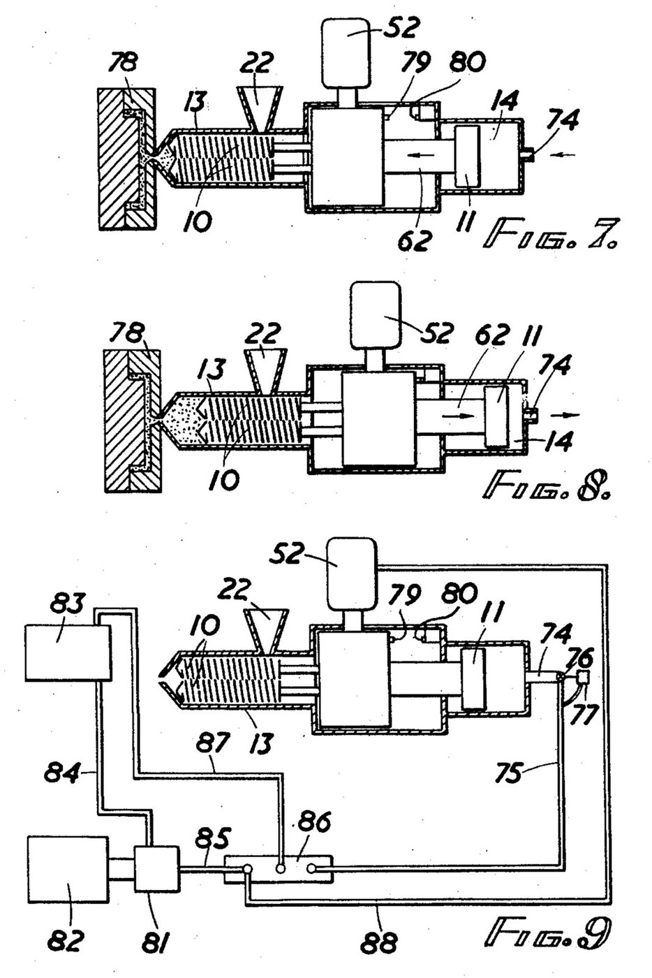


Injection Moulding Machine: Twin Intermeshing Screws as Plasticiser and Ram (Baigent, US 2,916,769)
An injection moulding machine melts plastic granules in a heated barrel and forces the melt into a mould. K. H. Baigent (US 2,916,769, 1959) does both jobs with one pair of intermeshing screws: turning, they melt, mix and pack the plastic at the nozzle; pushed forward by a hydraulic piston, they act as the ram.
Two screws are used because a single screw pushed as a ram lets too much melt flow back along its thread. At the outlet end each of his screws' threads nearly fills the gap in the other's, which seals against backflow.
Source: K. H. Baigent, "Injection Moulding Machines", US Patent 2,916,769 (filed 1957, granted 1959). Picture: its Figs. 7-9.
Advanced
Unknown
Instructions
1
1
Read Baigent
Read Baigent
"It has proven, as a practical matter, impossible to use a single screw as both an injection ram and a mixer or plasticiser, since when a single screw is translated forward to force the plastic material through the nozzle, a substantial portion thereof tends to flow backward between the threads of the screw."
2
2
Cut the twin screws
Cut the twin screws
Cut two intermeshing screws of the same outside diameter all along, so they can slide as a ram. Baigent's example: root diameter about 2.05 in., outside diameter about 3.06 in., pitch 1 in. In the outlet section the thread's outer face is about 0.30 in. deep axially with the leading face sloping 13° to the root, so each thread nearly fills the gap in the other screw. In the inlet section cut the leading face back to 31°, leaving 0.15 in., which gives about 1 1/2 times the swept volume of the outlet. Give each screw a splined end with a tapped bore. Screw length and metal are not given.
Materials for this step:
 Unknown Metal2 screws
Tools needed:
 Metal Lathe
 Milling Machine
 Tap and Die Set
 Unknown Dimensions
3
3
Make the barrel
Make the barrel
Bore a barrel (injection chamber) to take both screws side by side. Bolt a nozzle head on its outer end and screw in the injection nozzle. Cut a feed inlet near the other end under a hopper whose throat has a water-cooling jacket, so the granules do not melt before they enter. Wrap the barrel in closely spaced electric resistance heaters, with one more round the nozzle head. Clamp the barrel to its supports on the base. Bore, metal and heater ratings are not given.
Materials for this step:
Unknown Metal1 barrel, nozzle head and nozzleUnknown Metal1 hopper and water jacket Heating Element2 barrel and nozzle heaters
Tools needed:
Metal Lathe Drill Press
 Drill Bit SetTap and Die SetUnknown Dimensions
4
4
Build the sliding drive
Build the sliding drive
Build a gear box that slides on guide rails on a slide bed in line with the barrel. Run a hollow drive shaft for each screw in roller bearings, coupled to its screw by a splined sleeve and a tie rod through the shaft. Key a pinion on each shaft; both mesh inside opposite sides of one ring gear with internal teeth, so the screws turn at the same speed in the same direction. Cut worm teeth round the outside of the ring and drive it with a worm on the upright shaft of a hydraulic motor, in ball bearings.
Materials for this step:
Unknown Metal1 gear box, shafts, pinions, ring and worm Roller Bearing4 pieces
 Ball Bearing2 pieces
Tools needed:
Metal LatheMilling Machine Gear Hobbing Machine
 Adjustable Wrench
5
5
Fit the ram cylinder and hydraulics
Fit the ram cylinder and hydraulics
Bolt a hydraulic cylinder to the frame behind the gear box and bolt its piston rod to the gear box's thrust plate, so screws, gear box and piston slide as one. Feed the cylinder through a spring-loaded check valve, with a second, adjustable check valve on a branch that restricts the return flow: this sets the back pressure the melt must build before the screws are pushed back. An electric motor drives a hydraulic pump from a reservoir, through a solenoid-worked multiway pilot valve that sends oil either to the hydraulic motor or to the cylinder. Put a stop on the gear box and a limit switch where it ends its return stroke, and a time switch for the cooling period. Pressures are not given.
Materials for this step:
 Hydraulic Cylinder1 piece
 Check Valve (Non-Return)2 pieces
 Solenoid Valve1 multiway pilot valve
 Electric Motor1 pump drive
 Hydraulic Tubing1 piece
 Hydraulic Oil1 piece
Tools needed:
Adjustable Wrench6
6
Run a cycle
Run a cycle
Close the nozzle with the mould, fill the hopper with granules or powder and switch on the heaters to bring the barrel up to temperature. Start the hydraulic motor: the turning screws melt the plastic and pack it at the nozzle, and are forced back against the counter pressure until the stop trips the limit switch. The pilot valve then stops the motor and drives the piston forward, so the screws ram the melt into the mould. Everything stands still while the article cools; the time switch then restarts the motor for the next shot. How the mould is clamped and opened is not given.
Materials
10- 1 gear box, shafts, pinions, ring and wormPlaceholder
- 2 barrel and nozzle heatersPlaceholder
- 4 piecesPlaceholder
- Placeholder
- 1 piecePlaceholder
- 2 piecesPlaceholder
- Placeholder
- 1 pump drivePlaceholder
- 1 piecePlaceholder
- 1 piecePlaceholder
Tools Required
8- Placeholder
- Placeholder
- Placeholder
- Placeholder
- Placeholder
- Placeholder
- Placeholder
- Placeholder
This blueprint makes
CC0 Public Domain
This blueprint is released under CC0. You are free to copy, modify, distribute, and use this work for any purpose, without asking permission.
Support the Maker by purchasing products through their Blueprint where they earn a Maker Commission set by Vendors, or create a new iteration of this Blueprint and include it as a connection in your own Blueprint to share revenue.