ART
BEAUTY & WELLNESS
CRAFT
CULTURE & HISTORY
ENTERTAINMENT
ENVIRONMENT
FOOD & DRINKS
REVERSE ENGINEERING
SCIENCES
SPORTS
TECHNOLOGY
WEARABLES
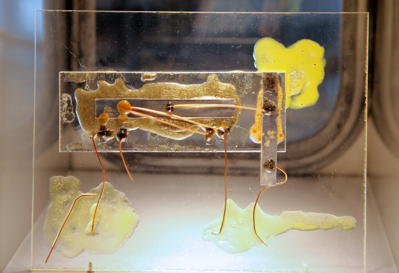


The Integrated Circuit — Kilby's Hybrid
In the summer of 1958 Jack Kilby was a new employee at Texas Instruments with no holiday entitlement, so he spent the company shutdown alone in an empty lab thinking about a problem the industry called the tyranny of numbers.
The problem was not making components. It was connecting them. A useful circuit needed hundreds of transistors, resistors and capacitors, each individually packaged, each soldered to a board by a person, each solder joint a chance to fail. Reliability fell as the count rose, so the complexity of a machine was limited not by what engineers could design but by how many hand-made connections would survive. Military systems were the sharpest case: a computer with a hundred thousand joints and a one-in-a-million joint failure rate fails constantly.
Everyone was attacking it by making the components smaller and the assembly more automatic. Kilby's insight was to attack the number of separate pieces instead. He noticed that although resistors and capacitors are ordinarily made of quite different materials from transistors, they CAN all be made out of semiconductor — a bar of doped silicon or germanium is a perfectly good resistor, and a reverse-biased junction is a perfectly good capacitor. They would be poor components by the standards of the day, expensive and imprecise. But they would all be made of the same material, in the same piece, at the same time.
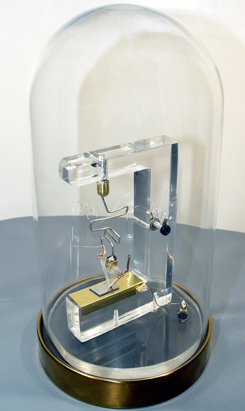
On 12 September 1958 he demonstrated it: a phase-shift oscillator with every component formed in a single sliver of germanium about 11 millimetres long, connected by fine gold wires bonded on by hand. It worked. The scope showed a clean sine wave.
And the hand-bonded wires are why this blueprint has a sibling. Kilby's chip proved the idea and could not be manufactured — every one of those connections was a person with a microscope and a probe, which is the very problem he set out to solve, merely relocated. Robert Noyce's answer at Fairchild four months later kept Kilby's insight and replaced the wires with printed metal. Both are integrated circuits. They are not the same invention, and the catalogue carries both because the comparison is the lesson.
Intermediate
5 hours
Instructions
1
1
Build every component out of one material
Build every component out of one material
Kilby's claim was that a resistor and a capacitor can be made from semiconductor rather than from carbon and mica. Test it, because the claim is easy to state and the consequences are not obvious until you have measured the components you get.
THE SEMICONDUCTOR RESISTOR. Any bar of doped semiconductor has resistance R equal to rho times L over A, where rho is the resistivity set by the doping. Take a length of doped material of known cross-section and measure it.
Without a fab, use what is at hand and measure honestly: a graphite pencil line on paper is a serviceable analogue for a diffused resistor, because both are bulk conduction through a resistive film whose value depends on geometry. Draw lines of the same width and different lengths with a soft pencil, pressing consistently, and measure end to end. Plot resistance against length; the slope gives you resistance per unit length, and dividing by the number of squares gives sheet resistance in ohms per square — exactly the quantity you measured with a four-point probe in the diffusion blueprint.
Then note the two problems that follow, because they are the reason integrated resistors are unpopular to this day. The ABSOLUTE value is poor: doping and thickness vary across a wafer, so a diffused resistor is typically specified to plus or minus 20 percent. The temperature coefficient is large, because carrier mobility falls as temperature rises. What IS good is the RATIO between two resistors made side by side, which tracks to a fraction of a percent because both see the same process variation. Analogue integrated design is built almost entirely on ratios for this reason.
THE JUNCTION CAPACITOR. A reverse-biased pn junction has a depletion region — a zone swept clear of mobile carriers — with conductive material either side. That is a capacitor, and its plate separation is the depletion width, which VARIES with applied voltage.
Measure it. Take a varicap diode, or any ordinary silicon diode which behaves the same way less dramatically. Build an LC oscillator with the diode reverse-biased as the tuning capacitor, and measure the frequency as you change the reverse bias from 1 to 9 volts. Frequency rises as bias rises, because the depletion region widens and capacitance falls. Convert your measured frequencies back to capacitance through the resonance formula.
You will find capacitance falls roughly as the inverse square root of voltage for an abrupt junction. That voltage dependence is a genuine nuisance in a circuit meant to have a fixed capacitor — and it is the entire operating principle of every varicap tuner ever built. The same physical fact is a defect or a feature depending on what you wanted.
That trade is Kilby's whole proposition: components that are individually worse, in exchange for being made together.
Materials for this step:
 Varicap Diode5 pieces
 Diode Small Signal - 1N414810 pieces
 Resistor Kit1 set
 Ceramic Capacitor Kit1 set
 Breadboard1 piece
 Graphite Pencil (6B)5 pieces
Tools needed:
 Digital Multimeter (Lab Grade)
 Oscilloscope (2-Channel, 100MHz)
 Bench Power Supply (30V/5A)
 Digital Calipers - 152.4 mm
2
2
Build Kilby's actual circuit — the phase-shift oscillator
Build Kilby's actual circuit — the phase-shift oscillator
Kilby chose a phase-shift oscillator for the demonstration, and the choice was deliberate: it needs a transistor, several resistors and several capacitors, so it exercises the claim that all three can be made in one material. Build it in discrete form first, so you know what the circuit does before you think about integrating it.
HOW IT OSCILLATES. An amplifier oscillates when the signal fed back to its input arrives in phase and at least as large as it started. A common-emitter transistor stage inverts, which is 180 degrees of the 360 you need. The remaining 180 comes from a ladder of three RC sections, each contributing up to 90 degrees but only reaching 60 degrees at the frequency where the ladder's loss is manageable — three times 60 is the 180 required. That is why there are exactly three sections: two cannot reach 180 at any frequency, and four is unnecessary hardware.
THE CIRCUIT. A single NPN transistor in common emitter — collector to the supply through 4.7 kilohms, emitter to ground through 470 ohms with a 10 microfarad bypass capacitor, base biased by a 100 kilohm and 22 kilohm divider. From the collector, three identical RC sections: 10 nanofarads in series, then 10 kilohms to ground, three times over. The output of the third section returns to the base.
The frequency is f = 1 / (2 pi R C sqrt(6)), which for 10 kilohms and 10 nanofarads gives about 650 hertz. The ladder attenuates by a factor of 29 at that frequency, so the transistor stage must have a voltage gain above 29 or nothing starts — and this is the commonest reason a first build sits silent. If it does, raise the collector resistor or reduce the emitter resistance.
Build it, put the scope on the collector, and confirm a clean sine wave near 650 hertz. Measure the actual frequency and compare it with the formula.
NOW DO THE THING THE BLUEPRINT IS ACTUALLY ABOUT. Count what you just built. Count the components, and separately count the CONNECTIONS — every lead into every breadboard hole is one joint. A discrete phase-shift oscillator has around ten components and roughly twenty-five connections.
Kilby's version had the same components and roughly a dozen connections, because the ones inside the germanium bar were formed rather than assembled. Now scale both numbers by a thousand, which is a modest computer of the period, and the difference stops being an efficiency and becomes the difference between a machine that can exist and one that cannot. That extrapolation is the tyranny of numbers, and doing the count yourself makes the argument in a way reading it does not.
Materials for this step:
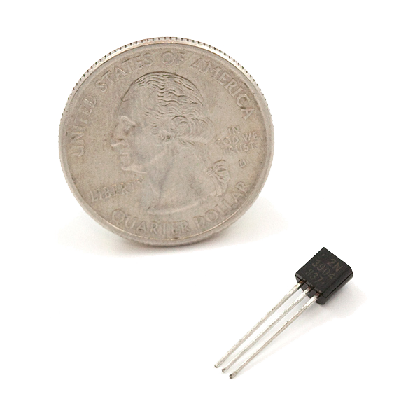 BJT Transistors - NPN 2N390410 piecesResistor Kit1 setCeramic Capacitor Kit1 set
 Electrolytic Capacitor Kit1 setBreadboard1 piece
 Jumper Wire Set1 set
Tools needed:
Oscilloscope (2-Channel, 100MHz)Digital Multimeter (Lab Grade)Bench Power Supply (30V/5A)3
3
The tyranny of numbers, counted
The tyranny of numbers, counted
Loading Jupyter Notebook...
Tools needed:
 Desktop Computer
4
4
Compendium — what Kilby got right, and what he did not
Compendium — what Kilby got right, and what he did not
WHAT WAS ACTUALLY NEW? Not the idea of many components in one piece — Geoffrey Dummer at the Royal Radar Establishment described that publicly in 1952 and failed to build it. What Kilby did was recognise that the components need not be GOOD, only compatible: a semiconductor resistor is worse than a carbon one and a junction capacitor is worse than a mica one, and it does not matter, because being made in the same operation beats being individually excellent. That is a judgement about systems rather than about devices, and it is the part that was hard.
WHY GERMANIUM? Texas Instruments was a germanium house and Kilby had germanium to hand during a shutdown. It was not the right long-term choice — germanium has no usable oxide, so the planar process could never have been applied to it — but for a two-week demonstration it was what existed.
WHY DID THE PATENTS COLLIDE? Kilby filed in February 1959 with claims covering electrical connections made by gold wires; Noyce filed in July 1959 with claims covering a planar structure with deposited metal interconnect over an insulating oxide. Both had valid claims to different aspects of the same idea. Litigation ran for a decade, the courts split the outcome, and in 1966 the companies simply cross-licensed. The industry proceeded on Noyce's method and paid royalties to both.
WHY DID KILBY ALONE GET THE NOBEL? He received it in 2000 for the integrated circuit. Noyce had died in 1990 and the prize is not awarded posthumously. Kilby said in his acceptance that if Noyce had been alive he would have shared it.
WHAT SURVIVED OF KILBY'S APPROACH? More than the potted history suggests. Hand-bonded wire is still how almost every chip connects to its package — the interconnect ON the chip is printed, but the connection from bond pad to package lead is a wire bonded by a machine doing what Kilby did by hand. And the hybrid concept — several dies and passive components on one substrate, wire-bonded together — never went away. It is how power modules, RF front ends and multi-chip modules are built today, and it has returned to prominence as chiplets, where a large design is split into several small dies precisely because of the yield arithmetic in the planar blueprint. Kilby's approach is not a dead end; it is a live branch that suits a different set of constraints.
WHAT SHOULD YOU TAKE FROM THE COMPARISON? That these two blueprints describe two genuinely different answers to one question, each with its own cost structure. Kilby's is faster to prototype, tolerates mixed materials, and scales its labour linearly with component count. Noyce's needs a far more elaborate process and then scales its labour not at all. For ten components in 1958, Kilby's was better. For a thousand, it was not. Knowing WHICH regime you are in is the whole skill, and it is why both remain in the catalogue.
Materials
9- 5 piecesPlaceholder
- Diode Small Signal - 1N414810% commission10 pieces$0.26
- Placeholder
- Placeholder
- Breadboard - Classic10% commission1 piece$9.38
- 5 piecesPlaceholder
- BJT Transistors - NPN 2N390410% commission10 pieces$0.76
- Placeholder
- 1 setPlaceholder
Tools Required
5- Placeholder
- Placeholder
- Placeholder
- Digital Calipers - 152.4 mm10% commission$14.06
- Placeholder
Estimated Total
What the maker bought. Materials shown without a price are sourced wherever you buy them.
Related Blueprints
These blueprints share knowledge with this one — techniques, materials, or principles that connect them in the learning graph.

CC0 Public Domain
This blueprint is released under CC0. You are free to copy, modify, distribute, and use this work for any purpose, without asking permission.
Support the Maker by purchasing products through their Blueprint where they earn a Maker Commission set by Vendors, or create a new iteration of this Blueprint and include it as a connection in your own Blueprint to share revenue.