Collaboration
ART
BEAUTY & WELLNESS
CRAFT
CULTURE & HISTORY
ENTERTAINMENT
ENVIRONMENT
FOOD & DRINKS
REVERSE ENGINEERING
SCIENCES
SPORTS
TECHNOLOGY
WEARABLES
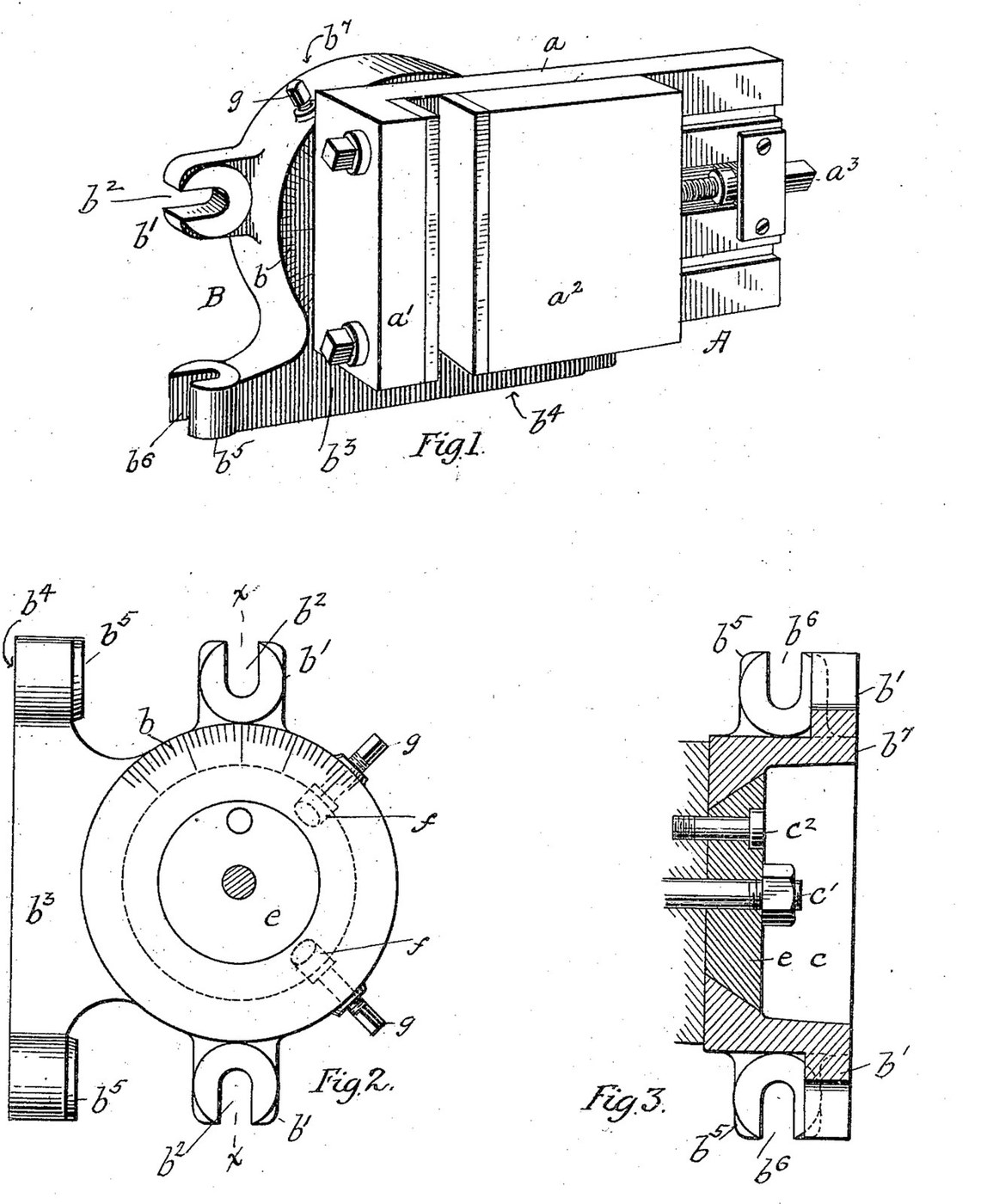


Milling Vise: Swivelled on a Two-Face Base with a Cone Seat and Locking Shoes (McClellan, US 652,441)
A milling vise holds the work on the table of a milling machine: a fixed jaw, a jaw moved by a screw, and a base that lets the vise swivel to any angle. E. J. McClellan (US 652,441, 1900) turns the vise on a cone-shaped disk in a matching seat in a cylindrical base, reads the angle on a scale, and locks it with two shoes screwed against the cone.
His base has two planed faces at right angles, each with its own bolt slots, so the vise can be bolted to the table lying flat or standing upright.
Source: E. J. McClellan, "Milling-Machine Vise", US Patent 652,441 (1900). Picture: its Figs. 1-3.
Advanced
Unknown
Instructions
1
1
Read McClellan
Read McClellan
"With such a construction it is possible to support the vise in one plane only, which plane is horizontal; but it is often found desirable to mount the vise in an upright position upon the slide in order to use the machine to the best advantage".
2
2
Make the base
Make the base
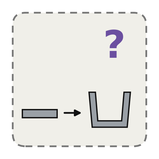
Make a cylindrical block. Plane one end face square to its axis to fit the machine table, with two ears at opposite points, slotted for bolts parallel to the axis. Give it a side extension with a second planed face at right angles to the first and parallel to the axis, with its own slotted ears, so the base can be bolted down on its end or on its side. Mark a scale round part of the opposite end face. Sizes, metal and how the scale is cut are not given.
Materials for this step:
 Unknown Metal1 base
Tools needed:
 Metal Planer
 Files (Hand File)
 Unknown Dimensions
 Unknown Forming Method
3
3
Cut the cone seat
Cut the cone seat
Bore a large central opening through the base and turn the end next to the scale into a conical seat, narrowest at the scaled face. Turn a disk with a matching conical edge. Drill two radial holes into the seat, ninety degrees apart, fit a shoe in each whose face forms part of the cone, and tap the holes behind them for adjusting screws.
Materials for this step:
Unknown Metal1 diskUnknown Metal2 shoesTools needed:
 Metal Lathe
 Drill Press
 Drill Bit Set
 Tap and Die Set
4
4
Make the vise
Make the vise
Make a plate carrying a fixed jaw, and a second plate as the sliding jaw, fitted to slide on the first and moved by a screw. Put an index mark on the vise to read against the base scale. The vise may be of any good construction; its sizes and the screw's thread are not given.
Materials for this step:
Unknown Metal1 plate and fixed jawUnknown Metal1 sliding jawUnknown Metal1 screwTools needed:
Metal PlanerMetal LatheDrill PressDrill Bit SetTap and Die SetUnknown Dimensions5
5
Assemble and set
Assemble and set
Pass the disk into its seat from below and bolt it to the vise plate with a centre bolt and an off-centre bolt. Bolt the base to the table on whichever face suits the job. To set an angle, slacken the bolts, swivel the vise to the scale, and screw the two shoes hard against the cone to lock it.
Materials for this step:
 Hex Bolt Assortment1 centre and off-centre bolts
Tools needed:
 Adjustable Wrench
Materials
2- 1 screwPlaceholder
- 1 centre and off-centre boltsPlaceholder
Tools Required
9- Placeholder
- Placeholder
- Placeholder
- Placeholder
- Placeholder
- Placeholder
- Placeholder
- Placeholder
- Placeholder
This blueprint makes

CC0 Public Domain
This blueprint is released under CC0. You are free to copy, modify, distribute, and use this work for any purpose, without asking permission.
Support the Maker by purchasing products through their Blueprint where they earn a Maker Commission set by Vendors, or create a new iteration of this Blueprint and include it as a connection in your own Blueprint to share revenue.