ART
BEAUTY & WELLNESS
CRAFT
CULTURE & HISTORY
ENTERTAINMENT
ENVIRONMENT
FOOD & DRINKS
REVERSE ENGINEERING
SCIENCES
SPORTS
TECHNOLOGY
WEARABLES
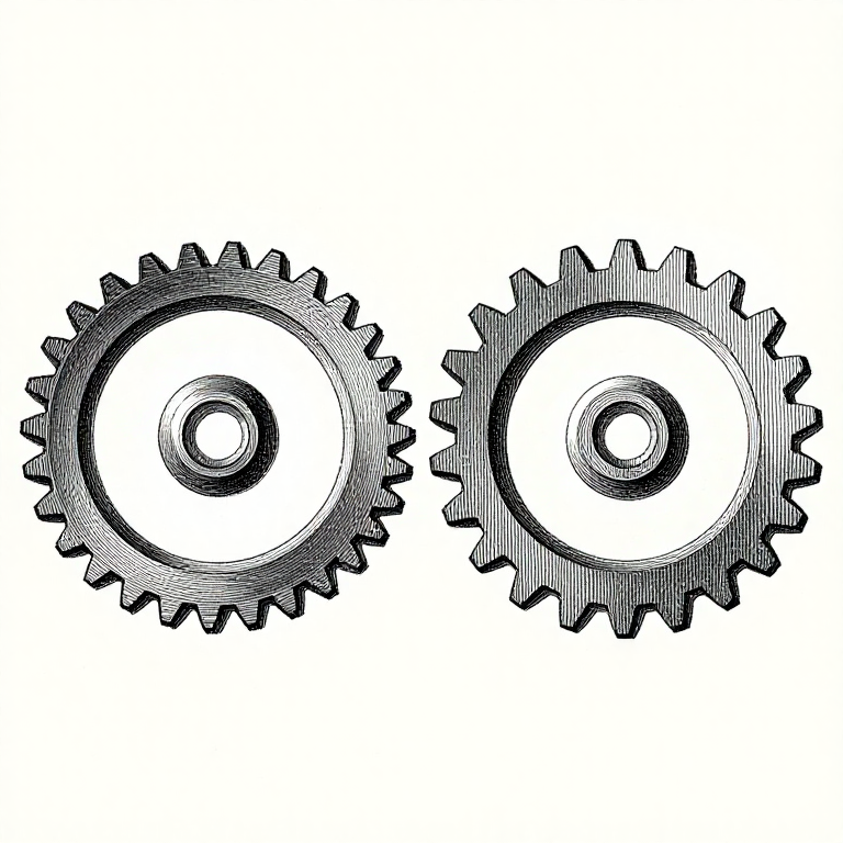


Module and Pitch: The One Number Two Gears Must Share
Two gears mesh only if their teeth are the same size, and that size is the first thing specified about any gear. Everything else — the diameter, the centre distance, the strength — follows from it and the tooth count.
It is written two incompatible ways. **Module** is millimetres of pitch diameter per tooth, so a bigger number means bigger teeth. **Diametral pitch** is teeth per inch of pitch diameter, so a bigger number means smaller teeth. They run in opposite directions and they do not interconvert to standard values, which is why a metric gear and an inch gear will not run together.
This rung is that language, how to identify an unknown gear with a caliper, and how module relates to strength.
Intermediate
3 hours
Instructions
1
1
The circles a gear is described by
The circles a gear is described by
A gear has several diameters and only one of them matters for meshing.
**The pitch circle** is where two meshing gears effectively roll on each other without slipping. It is the gear as far as kinematics is concerned — the ratio, the centre distance and the pitch line velocity are all about this circle. It is also invisible: there is nothing on the gear at that diameter.
**The addendum circle** is the outside, over the tips. One module above the pitch circle for a standard tooth, so the outside diameter is m(z + 2).
**The dedendum circle** is the root, at the bottom of the tooth spaces. 1.25 modules below the pitch circle, the extra quarter giving clearance for the tip of the mating tooth.
**The base circle** is where the involute curve starts, and the next rungs need it.
**Circular pitch** is the distance from one tooth to the next measured round the pitch circle: π times the module. It is the intuitive measure and it is awkward arithmetically, which is why module exists — module is circular pitch divided by π, chosen so the numbers come out round.
Materials for this step:
 Spur Gear Set (Steel, 20 Tooth)1 piece
Tools needed:
 Digital Caliper 6-Inch
 Steel Ruler
2
2
The arithmetic, and identifying an unknown gear
The arithmetic, and identifying an unknown gear
Loading Jupyter Notebook...
Tools needed:
 Desktop Computer
3
3
Measuring a gear you have
Measuring a gear you have
**Count the teeth.** Mark one with a pen and count round. It sounds trivial and it is the single most common error, because a gear with 41 teeth looks exactly like one with 40.
**Measure the outside diameter** with a caliper. On an even tooth count, measure tip to tip straight across. On an **odd** count there is no tooth opposite a tooth, so a direct measurement reads low — measure over the bore or use the formula with the tooth count, and the arithmetic is more reliable than the caliper.
**Then module = outside diameter divided by (teeth + 2)**, and round to the nearest standard.
**Check the tooth height** as a confirmation: a standard full-depth tooth is 2.25 modules from root to tip. If the height does not agree with the module the diameter suggested, the gear is a stub tooth form or it has been cut with addendum modification.
**Measure the face width and the bore** too, and write all of it down together. A gear identified but not recorded is a gear that will be identified again next month.
Materials for this step:
Spur Gear Set (Steel, 20 Tooth)1 pieceTools needed:
Digital Caliper 6-Inch Vernier Caliper
 Micrometer
 Change Gear Set
4
4
Why the standard sizes are standard
Why the standard sizes are standard
**Gears are cut with tools that are specific to the module**, and that is the whole reason for standardisation.
A hob or a cutter cuts one module. A set of involute cutters for one module comes in eight numbers, each covering a range of tooth counts, because the correct involute shape changes with the number of teeth — a cutter for a 20-tooth gear is visibly a different shape from one for a 100-tooth gear of the same module.
So a non-standard module means a special cutter, and a special cutter costs more than the machine time for the gear.
**Prefer the standard series**, which is why the notebook's list looks like it does: 1, 1.25, 1.5, 2, 2.5, 3, 4, 5, 6, 8, 10. The intermediate sizes exist and are much less available.
**Inch gears are quoted in diametral pitch** — 24 DP, 20 DP, 16 DP — and are everywhere in older machinery and in model engineering. A 24 DP gear is module 1.058, which is not a standard module, so the two families genuinely do not interchange.
**Check what the rest of the machine uses before choosing.** A gearbox with one odd module in it is a gearbox that cannot be repaired from stock.
Tools needed:
Digital Caliper 6-InchChange Gear SetMaterials
1- Placeholder
Tools Required
6- Placeholder
- Placeholder
- Placeholder
- Placeholder
- Placeholder
- Placeholder
Related Blueprints
These blueprints share knowledge with this one — techniques, materials, or principles that connect them in the learning graph.


CC0 Public Domain
This blueprint is released under CC0. You are free to copy, modify, distribute, and use this work for any purpose, without asking permission.
Support the Maker by purchasing products through their Blueprint where they earn a Maker Commission set by Vendors, or create a new iteration of this Blueprint and include it as a connection in your own Blueprint to share revenue.