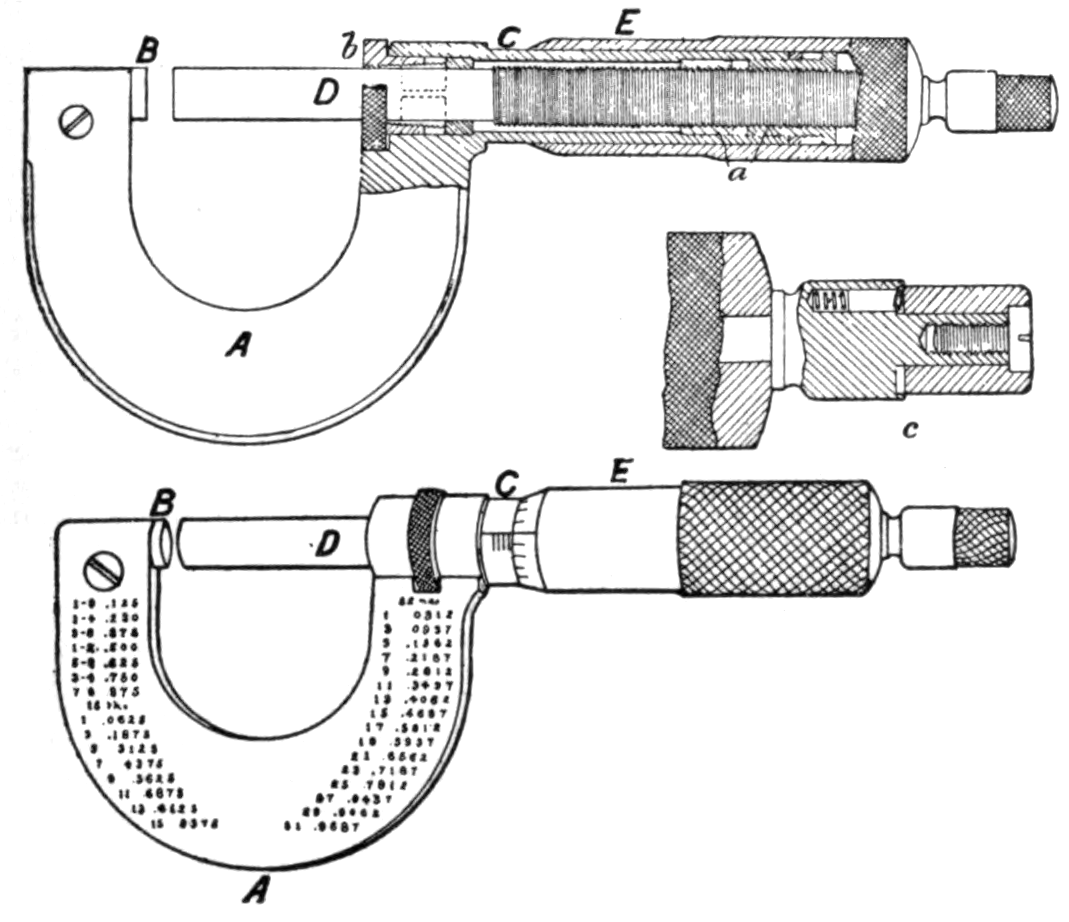


Micrometer Caliper
A workshop cannot make two identical parts if it cannot measure a thousandth. The micrometer is the instrument that made the interchangeable part possible.
French patent no. 7,518, granted 7 September 1848 to Jean Laurent Palmer, for the “Système Palmer”. The idea is simple and profound: a screw of known pitch converts a rotation, which can be divided finely around a large circle, into a minute displacement. If the screw advances 0.5 mm per turn and the thimble carries 50 divisions, each division is 0.01 mm.
What the legend gets wrong. It is written everywhere that Brown & Sharpe invented or patented the micrometer in 1867. They did not. Joseph R. Brown and Lucien Sharpe saw the Système Palmer at the Paris Exposition of 1867, bought one, and copied the principle; their instrument reached the market in 1868-69. The patent is Palmer's, and it is twenty years older.
Instructions
Understand the claim before you build
Understand the claim before you build
Palmer does not claim “a measuring clamp”. He claims an amplification: a screw of known pitch converts a large, easily read angle into a small, hard-to-read displacement. Write that sentence down before you start.
Measure the pitch of a screw
Measure the pitch of a screw
Take a #6-32 screw. Count 10 turns as you drive it in and measure the total advance with the rule. Divide by 10: that is the pitch.
Materials for this step:
 #6-32 Machine Screw1 piece
Tools needed:
 Steel Ruler (30cm)
Calculate the thimble division
Calculate the thimble division
Pitch divided by the number of thimble divisions = smallest reading. Write the calculation on the graph paper. For 0.5 mm and 50 divisions: 0.01 mm.
Materials for this step:
 Graph Paper1 sheet
Draw a thimble of 50 divisions
Draw a thimble of 50 divisions
With the protractor, draw a circle 60 mm across and divide it into 50 equal parts (7.2° each). Cut it out.
Materials for this step:
Graph Paper1 sheetTools needed:
 Protractor
 Sharp Scissors
Mount the thimble on the screw
Mount the thimble on the screw
Glue the disc to the head of the screw, well centred. Leave it to set for 10 minutes.
Materials for this step:
 Wood Glue3 ml
Build the frame
Build the frame
Drill a pilot hole in the board and drive the screw into it so it advances against a fixed anvil. This is Palmer's frame, in wood.
Materials for this step:
 Flat Wooden Board1 piece
Tools needed:
 Drill Bit Set
Mark a fixed index
Mark a fixed index
Draw a reference line on the board at the edge of the thimble. Without an index, a graduation means nothing.
Tools needed:
 Permanent Marker
Calibrate to zero
Calibrate to zero
Drive the screw until it touches the anvil. Turn the thimble to bring zero opposite the index. An uncalibrated instrument lies precisely.
Measure a sheet of foil
Measure a sheet of foil
Insert the foil, drive the screw to light contact, read turns + divisions. Convert to millimetres.
Materials for this step:
 Aluminium Foil1 sheet
Measure a stack of ten sheets
Measure a stack of ten sheets
Stack ten sheets, measure, divide by ten. Compare with the single measurement: the difference is your reading error, not the thickness of the metal.
Materials for this step:
Aluminium Foil10 sheetsCompare with a real micrometer
Compare with a real micrometer
Measure the same sheet with the workshop micrometer. Note the difference against your wooden model.
Tools needed:
 Micrometer
Squeeze too hard, deliberately
Squeeze too hard, deliberately
Take the measurement again, forcing it. The reading changes: you are crushing the material. This defect will be solved forty years later by Starrett's spring.
Materials for this step:
Aluminium Foil1 sheetHave someone else measure it
Have someone else measure it
Ask another person to measure the same sheet. The difference between the two of you is the real industrial problem: a measurement must be reproducible, not merely fine.
Materials for this step:
Aluminium Foil1 sheetHistory & Context
History & Context
French patent no. 7,518, Jean Laurent Palmer, 7 September 1848, granted by the Ministry of Agriculture and Commerce.
Palmer presented a screw-micrometer caliper that could be read directly, with no table and no calculation. The instrument saw little uptake in France.
The correction that matters. Countless sources credit the invention to Brown & Sharpe in 1867. The facts: J. R. Brown and L. Sharpe discovered the Système Palmer at the Paris Exposition of 1867, bought an example, and drew on it for a sheet-metal gauge; their pocket micrometer appeared in 1868-69. They industrialised and popularised the instrument — which is considerable — but they did not invent it. Repeating the legend erases Palmer from a verifiable fact.
Why this instrument changes everything. As long as a fitter works “by feel”, every part is unique and every repair demands fitting. The moment the workshop can read a hundredth, a tolerance can be written down, and a written tolerance is what makes a part interchangeable. The vernier, linked here, gave the fraction; the micrometer screw gives the thousandth.
Materials
5- 1 piecePlaceholder
- 1 sheetPlaceholder
- 3 mlPlaceholder
- 1 piecePlaceholder
- 13 sheetsPlaceholder
Tools Required
6- Placeholder
- Placeholder
- Placeholder
- Placeholder
- Placeholder
- Placeholder
Connected Blueprint Materials
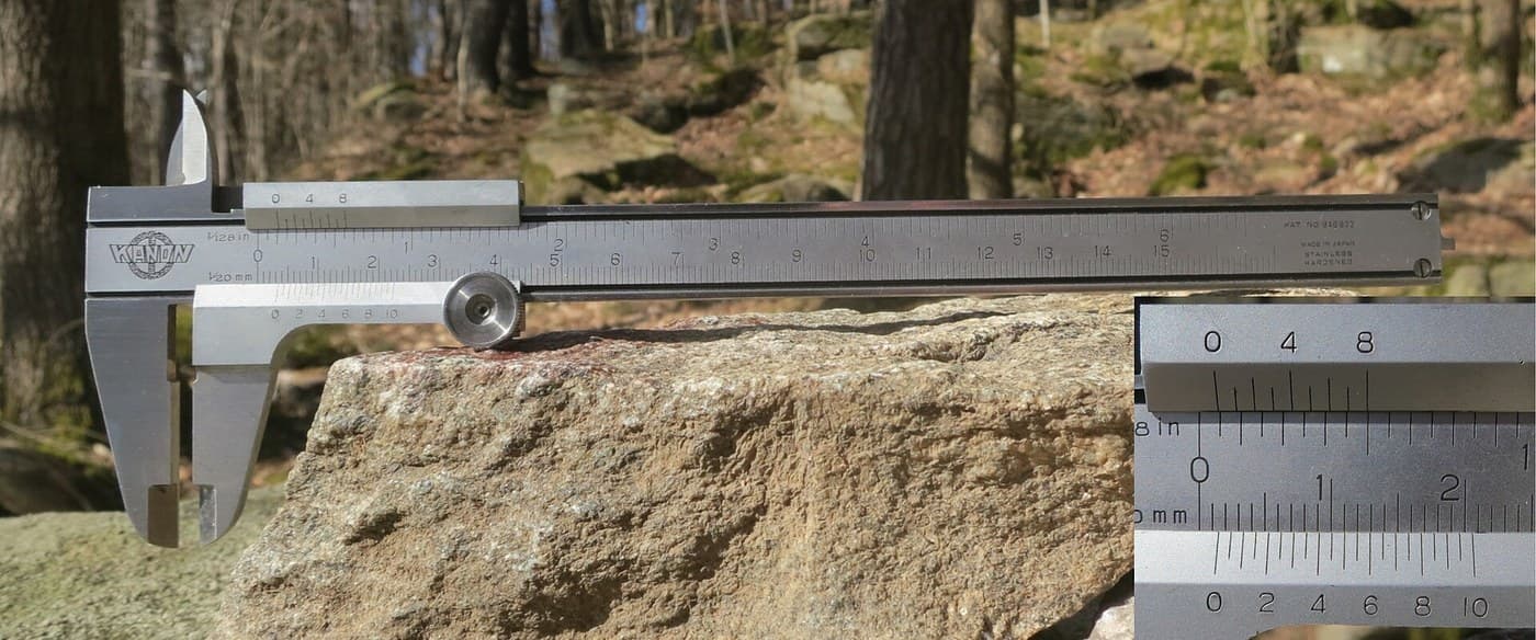

Related Blueprints
These blueprints share knowledge with this one — techniques, materials, or principles that connect them in the learning graph.


CC0 Public Domain
This blueprint is released under CC0. You are free to copy, modify, distribute, and use this work for any purpose, without asking permission.
Support the Maker by purchasing products through their Blueprint where they earn a Maker Commission set by Vendors, or create a new iteration of this Blueprint and include it as a connection in your own Blueprint to share revenue.