Collaboration
ART
BEAUTY & WELLNESS
CRAFT
CULTURE & HISTORY
ENTERTAINMENT
ENVIRONMENT
FOOD & DRINKS
REVERSE ENGINEERING
SCIENCES
SPORTS
TECHNOLOGY
WEARABLES
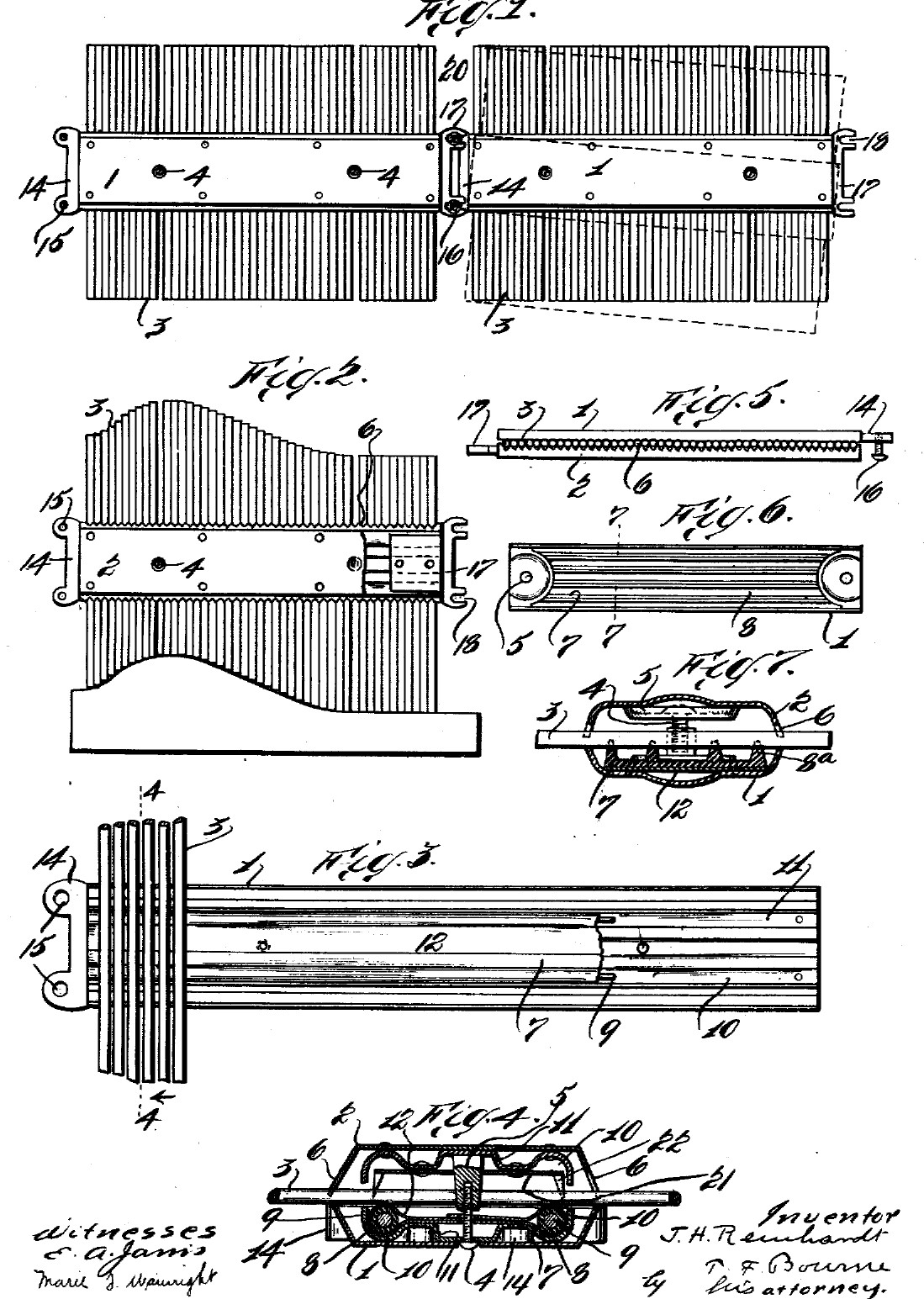


Profile Gauge: Sliding Pins Held by Cloth-Wrapped Rubber Tubes (Reinhardt, 1918)
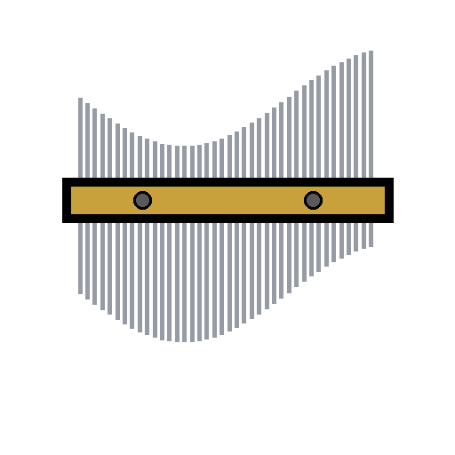
James H. Reinhardt of East Orange, New Jersey, received US 1,261,438, dated 2 April 1918, for a profile gauge: a row of pins clamped between two thin metal members. Rubber tubes wrapped in cloth press on the pins, so each one slides when pushed and stays where it is left. Pressed against an object, the pin ends take its outline, and a pencil drawn along them copies it, so the shape can be made again.
We build his single gauge from brass sheet and steel wire. All sizes are ours.
Intermediate
About 5 hours
Instructions
1
1
How many pins
How many pins
Loading Jupyter Notebook...
2
2
Read US 1,261,438
Read US 1,261,438
"The rods or pins 3 of the respective gages may be pushed against the surface of the object, as required, to obtain its outline along the ends of the rods or pins, whereby a pencil may be drawn along the ends of the pins to trace such outline or contour of the object. From such outlines objects corresponding to the master object may be reproduced either in relief or concave according to which way the outline drawn from the ends of the rods is used."
3
3
Make the two members
Make the two members
Cut two strips of 0.8 mm brass sheet 200 x 32 mm (ours) with tin snips and file the edges. Bend 4 mm down along each long side in the vice, so each strip becomes a shallow channel 24 mm wide: his "gutter-like form". Clamp them together, open sides facing, and drill a 3.5 mm hole through both, 50 mm from each end, on the middle line.
Materials for this step:
 Brass Sheet2 pieces
Tools needed:
 Tin Snips
 File Set
 Bench Vise
 Scriber
 Hand Drill
4
4
Make the gutters
Make the gutters
Cut two strips of the same brass 180 x 14 mm and bend each round a 6 mm rod into a U that will hold the rubber tube, his gutters 10. Rivet them inside one member, one near each long side, with copper rivets, keeping clear of the screw holes.
Materials for this step:
Brass Sheet1 piece Copper Rivets6 pieces
Tools needed:
Tin Snips Mild Steel RodBench ViseHand Drill
 Ball Peen Hammer
5
5
Make the retainers
Make the retainers
Cut two pieces of 6 mm rubber tubing 170 mm long and push a 2 mm wire through each, his cores 9, "to somewhat stiffen them". Wrap each in a strip of cotton cloth, lap its edges and glue them with contact cement, his protecting cloth 12, so the rubber does not touch the metal. Lay one in each gutter.
Materials for this step:
 Rubber Tubing1 piece
 Steel Wire1 piece
 Cotton Cloth1 piece
 Contact Cement1 piece
Tools needed:
 Wire Cutters
 Scissors
6
6
Cut the pins
Cut the pins
Cut 1 mm steel wire into pins 120 mm long, as many as the notebook gives. Straighten any that are bent and file both ends flat and smooth, so they slide easily and do not mark the work.
Materials for this step:
Steel Wire1 pieceTools needed:
Wire Cutters Needle File SetBench Vise
7
7
Assemble
Assemble
Lay the member with the retainers open side up. Lay the pins across it side by side, touching, centred so equal lengths stick out on both sides; leave a gap at each screw hole (ours). Put the other member on top and pass a machine screw through each hole with a nut. Tighten them evenly until each pin slides when pushed but does not fall.
Materials for this step:
 Machine Screws2 pieces
 Hex Nut2 pieces
Tools needed:
 Screwdriver Set
 Adjustable Spanner
8
8
Take a profile
Take a profile
Push all the pins level with a flat board. Press the gauge square against the object until the pins have taken its shape. Lift it off, lay it on paper or on the stock to be cut, and draw a pencil along the pin ends.
Tools needed:
 Pencil
9
9
Troubleshooting
Troubleshooting
Pin profile gauge troubleshooting.
Flow
Loading...
10
10
History and honest limits
History and honest limits
**James H. Reinhardt** of East Orange, New Jersey, US 1,261,438, dated 2 April 1918, filed 20 June 1914. He claimed "a profile gage comprising a pair of opposed members, rods or pins located between and transversely with respect to said members, means for clamping said members together" and "a resilient retainer comprising spaced rubber tubes". His members can have teeth along their edges, and his patent also covers end castings that join several gauges in a line or at an angle, a smaller gauge clamped between them, a toothed spacer strip and a rubber-mat retainer: none of those are built here. He gives no sizes: the brass, the 200 mm length, the 1 mm pins, the tube and core sizes, the cement, the rivets and the screws are ours.
Materials
8- 2 piecesPlaceholder
- 6 piecesPlaceholder
- 1 piecePlaceholder
- 2 piecesPlaceholder
- 1 piecePlaceholder
- 1 piecePlaceholder
- 2 piecesPlaceholder
- 2 piecesPlaceholder
Tools Required
13- Placeholder
- Placeholder
- Placeholder
- Placeholder
- Placeholder
- Placeholder
- Placeholder
- Placeholder
- Placeholder
- Placeholder
- Placeholder
- Placeholder
- 1 vendor sell this, none ship to you yetPlaceholder
This blueprint makes
Related Blueprints
These blueprints share knowledge with this one — techniques, materials, or principles that connect them in the learning graph.

CC0 Public Domain
This blueprint is released under CC0. You are free to copy, modify, distribute, and use this work for any purpose, without asking permission.
Support the Maker by purchasing products through their Blueprint where they earn a Maker Commission set by Vendors, or create a new iteration of this Blueprint and include it as a connection in your own Blueprint to share revenue.