ART
BEAUTY & WELLNESS
CRAFT
CULTURE & HISTORY
ENTERTAINMENT
ENVIRONMENT
FOOD & DRINKS
REVERSE ENGINEERING
SCIENCES
SPORTS
TECHNOLOGY
WEARABLES
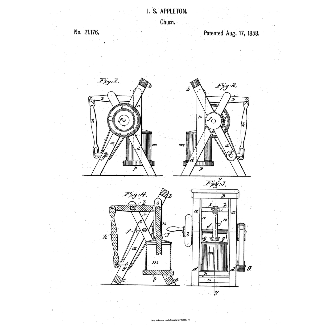


Swinging-Vessel Crank Churn: The Churn Hangs Free and Follows Its Crank-Driven Dasher
James S. Appleton of White River Junction, Vermont, received US 21,176, dated 17 August 1858, for a churn hung in a freely swinging frame while a crank, pitman and vibrating beam work its dasher, so the vessel follows the dasher's swing and the dasher can run fast without binding in the vessel or its cover.
This rung builds the crossed frame in pine and prints the vessel, beam, crank and band pulleys at tabletop scale.
Advanced
About 8 hours, plus printing
Instructions
1
1
Band, crank and beam
Band, crank and beam
Loading Jupyter Notebook...
2
2
Hanging churns, before it
Hanging churns, before it
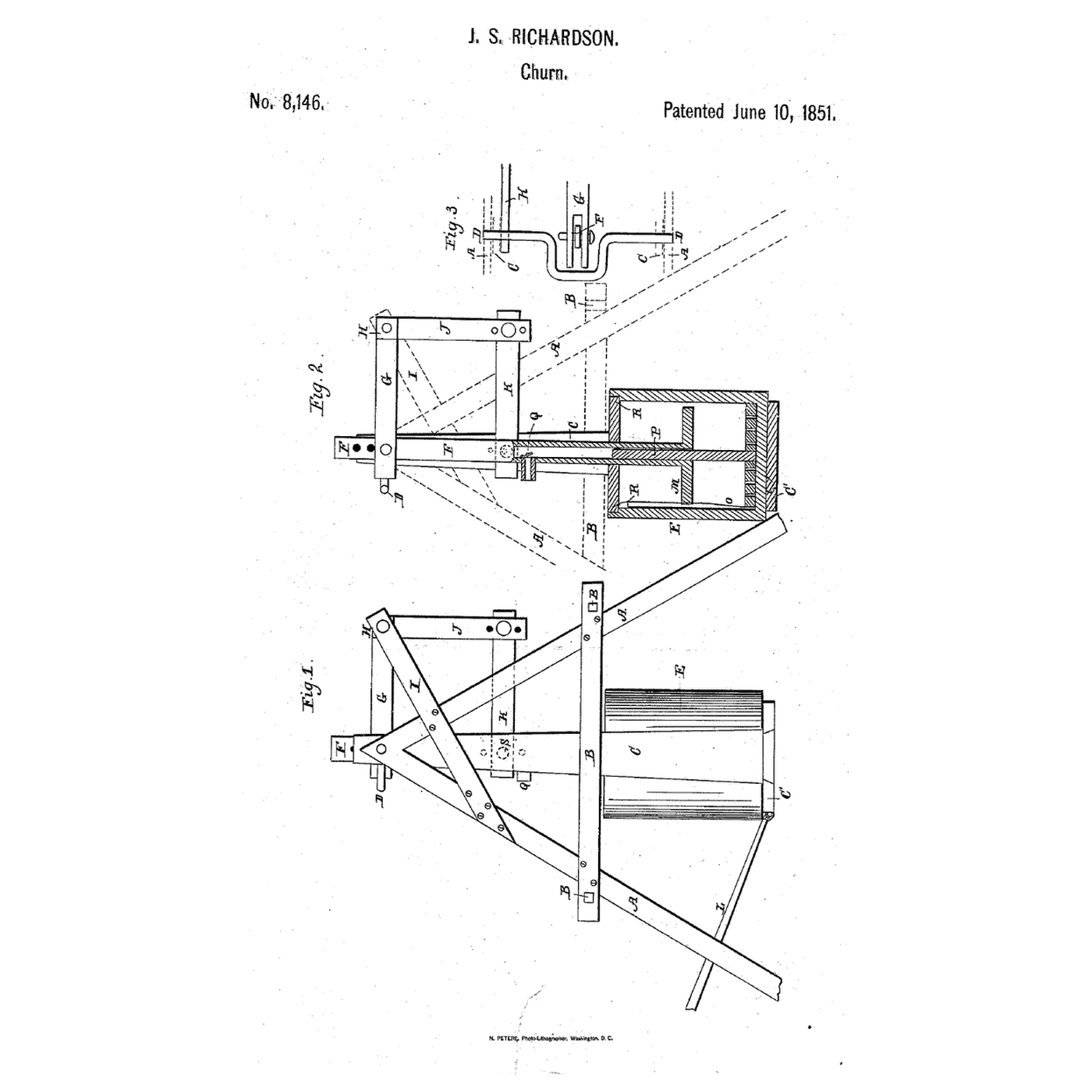
There the hanging tank was rocked by hand; here it swings free while a crank works the dasher.
3
3
Read US 21,176
Read US 21,176
"The churning vessel m, being allowed to swing freely back and forth during the operation of its dasher, will prevent any binding or grinding friction between the sides of said dasher and the sides of the churning vessel…"
4
4
Print the parts
Print the parts
Print the vessel (/uploads/blueprints/swinging-vessel-crank-churn-vessel.stl), its cover (/uploads/blueprints/swinging-vessel-crank-churn-cover.stl), the disk (/uploads/blueprints/swinging-vessel-crank-churn-disk.stl), two bridles (/uploads/blueprints/swinging-vessel-crank-churn-bridle.stl), two buttons (/uploads/blueprints/swinging-vessel-crank-churn-button.stl), the dash (/uploads/blueprints/swinging-vessel-crank-churn-dash.stl), the dasher head (/uploads/blueprints/swinging-vessel-crank-churn-dasher-head.stl), the beam (/uploads/blueprints/swinging-vessel-crank-churn-beam.stl), the pitman (/uploads/blueprints/swinging-vessel-crank-churn-pitman.stl), two crank webs (/uploads/blueprints/swinging-vessel-crank-churn-crank-web.stl), the large (/uploads/blueprints/swinging-vessel-crank-churn-pulley-large.stl) and small (/uploads/blueprints/swinging-vessel-crank-churn-pulley-small.stl) pulleys, the balance wheel (/uploads/blueprints/swinging-vessel-crank-churn-balance-wheel.stl) and the handle (/uploads/blueprints/swinging-vessel-crank-churn-handle.stl). Lay the bridles, beam and pitman across the bed's diagonal. Print in PETG at 0.2 mm layers, 30 % infill, 4 walls; wash before first use.
Materials for this step:
 PETG Filament1 piece
Tools needed:
 FDM 3D Printer
5
5
The crossed frame
The crossed frame
Rip 18 mm pine into 30 mm strips. For each side cut a timber a 406 mm long and a timber d 367 mm long, and halve them where they cross, 227 mm along a and 205 mm along d from their lower ends; glue and screw. Join the two sides 170 mm apart inside with cross pieces 206 mm long at the top of a and the feet of a and d. Drill 10.5 mm holes through both sides where the timbers cross, through a 81 mm from its foot, and through d 15 mm from its top; and a 4.5 mm hole through a 363 mm from its foot for the bridles.
Materials for this step:
 Pine Board1 piece
 Wood Glue1 piece
 Wood Screws1 piece
Tools needed:
 Hand Saw
 Cordless Drill
 Sandpaper
 Screwdriver Set
 Tape Measure
6
6
Shafts, band and beam
Shafts, band and beam
Cut 10 mm dowels: the driving shaft 276 mm, the beam's shaft 216 mm, and the crank shaft in two pieces of 102 and 142 mm. Pass the driving shaft through the crossing holes and fix the large pulley and the balance wheel on its front end with M3 screws drilled through. Fix a crank web on the inner end of each crank-shaft piece, an M6 screw through both webs as the crankpin, and the small pulley on the front end. Tie a loop of cotton twine tightly over both pulleys as the band. Put the beam on its shaft between the d timbers, the pitman from the crankpin to the beam's fork on an M6 screw, and screw the handle into the balance wheel.
Materials for this step:
 Hardwood Dowels1 piece
 Machine Screws1 piece
 Nylon Insert Lock Nut1 piece
 Flat Washer1 piece
 Cotton Twine1 piece
Tools needed:
Hand SawCordless DrillScrewdriver Set7
7
Swinging vessel and dasher
Swinging vessel and dasher
Hang a bridle from each a on an M4 screw through the 4.5 mm hole, free to swing, and bolt the disk between their feet. Stand the vessel on the disk. Cut a 10 mm dowel 194 mm long as the dasher shaft, fix the dash on its foot and the head on its top, pass it through the cover, and pin the head into the beam's other fork with an M6 screw and lock nut, your removable pin. Turn the buttons over the cover.
Materials for this step:
Hardwood Dowels1 pieceMachine Screws1 pieceNylon Insert Lock Nut1 pieceTools needed:
Hand SawScrewdriver Set8
8
The build in 3D
The build in 3D
FreeCAD model of this build: the crossed pine frame, the vessel hung on its bridles and disk, the cover and buttons, the dasher on the vibrating beam, the pitman from the crank between its webs, the band pulleys on the driving and crank shafts, and the balance wheel with its handle.
9
9
Churn
Churn
Pour in 1.2 litres of heavy cream at about 15 °C, checked with the thermometer, set the cover on and turn the buttons. Turn the handle steadily and time it with the stopwatch: the vessel swings a little with each stroke. When the butter comes, pull the pin, lift the dasher and the vessel out, pour off the buttermilk, wash the butter in cold water until it runs clear, work in a pinch of salt and weigh it.
Materials for this step:
 Heavy Cream1.2 l
 Coarse Sea Salt1 piece
 Water1 piece
Tools needed:
 Leave-In Probe Thermometer
 Stopwatch
 Digital Kitchen Scale
 Stainless Steel Mixing Bowl (Large)
10
10
Troubleshooting
Troubleshooting
Swinging-vessel churn troubleshooting.
Flow
Loading...
11
11
History and honest limits
History and honest limits
**James S. Appleton** of White River Junction, Windsor County, Vermont, US 21,176, 17 August 1858, signed 17 June 1858. Any form of dasher, he wrote, may be used, and the shafts may be geared instead of banded. He held that the swinging, pulsing vessel makes the dasher act with unusual energy, and claimed securing the vessel in a freely swinging frame while a crank shaft, pitman and vibrating beam work the dasher. Our frame sizes, printed parts, cord band and dash are ours. FDM prints hold food in their layer lines, so wash well and replace when worn.
Materials
12- 1 piecePlaceholder
- 1 piecePlaceholder
- 1 piecePlaceholder
- 1 piecePlaceholder
- 1 piecePlaceholder
- 2 piecesPlaceholder
- 2 piecesPlaceholder
- 1 piecePlaceholder
- 1 piecePlaceholder
- 1.2 lPlaceholder
- 1 piecePlaceholder
- 1 piecePlaceholder
Tools Required
10- Placeholder
- Placeholder
- 1 vendor sell this, none ship to you yetPlaceholder
- Placeholder
- Placeholder
- 1 vendor sell this, none ship to you yetPlaceholder
- Placeholder
- Placeholder
- Placeholder
- Placeholder
Design Files
1Related Blueprints
These blueprints share knowledge with this one — techniques, materials, or principles that connect them in the learning graph.

CC0 Public Domain
This blueprint is released under CC0. You are free to copy, modify, distribute, and use this work for any purpose, without asking permission.
Support the Maker by purchasing products through their Blueprint where they earn a Maker Commission set by Vendors, or create a new iteration of this Blueprint and include it as a connection in your own Blueprint to share revenue.