ART
BEAUTY & WELLNESS
CRAFT
CULTURE & HISTORY
ENTERTAINMENT
ENVIRONMENT
FOOD & DRINKS
REVERSE ENGINEERING
SCIENCES
SPORTS
TECHNOLOGY
WEARABLES
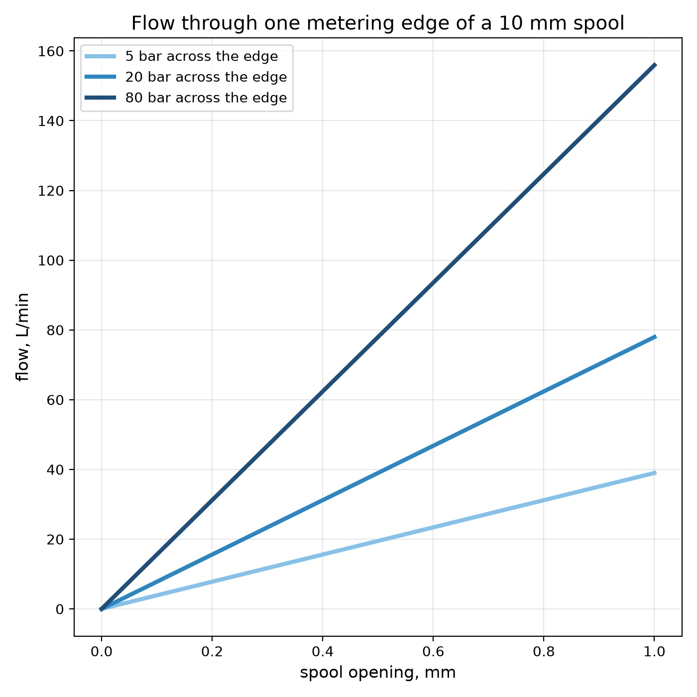
Youblob (generated from this blueprint's notebook) · CC0

The Spool Valve: Steering Oil With a Sliding Rod
A pump makes flow and a cylinder makes force. Between them sits the valve that decides where the oil goes: to one end of the cylinder, to the other, or back to the tank. In almost every hydraulic machine that valve is a **spool**: a ground steel rod with raised lands, sliding in a bore with five ports — pressure, tank, two work ports, and a second tank.
Slide the spool one way and pressure goes to port A while B drains; slide it the other way and the roles swap; centre it and the ports are blocked or joined, depending on the spool's centre. The edges of the lands are orifices, so the spool also meters how fast.
This rung works out the metering, the choice between open and closed centre, and builds a transparent spool valve that shows the oil paths in coloured water.
Intermediate
About 4 hours
Instructions
1
1
Metering edges and the centre condition
Metering edges and the centre condition
Loading Jupyter Notebook...
2
2
Each land edge is a throttle
Each land edge is a throttle
The spool meters flow the way any restriction does. The embedded blueprint shows how flow through a restriction depends on its area and the pressure across it.
3
3
Build a clear spool valve
Build a clear spool valve
Take 150 mm of clear acrylic tube with a smooth 20 mm bore. Drill five 6 mm holes in a line along one side, 20 mm apart, and glue a hose barb over each: from one end, **T**, **A**, **P**, **B**, **T**.
3D-print a spool: a 10 mm shaft carrying three lands, each 12 mm long with an O-ring groove, spaced so that when the spool is centred the middle land exactly covers **P** and the outer lands cover **A** and **B**. Fit O-rings sized to seal lightly in the bore. A handle on one end, a stop on the other.
Connect **P** to a garden hose through a ball valve, the two **T** ports to a bucket, and **A** and **B** to the two ports of the double-acting cylinder, or to two clear tubes standing up so you can see which one fills.
Materials for this step:
 Acrylic Tube (Clear)1 piece
 PVC Pipe Fittings Assortment1 piece
 O-Ring Assortment Kit1 piece
 Silicone Tubing2 meters
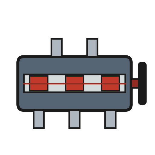 Directional Control Valve1 piece
Tools needed:
 FDM 3D Printer
 PETG Filament
 Cordless Drill
 Drill Bit Set
 Digital Caliper 6-Inch
 Hot Glue Gun
 Bucket
4
4
The three positions
The three positions
Blockly Workspace
Loading Blockly workspace...
5
5
Run it with coloured water
Run it with coloured water
Add food colouring to a bucket feeding a small submersible pump, or tint the hose supply with a dye injector, so the flow shows in the clear bore.
Centre the spool and open the supply: nothing moves, and the supply hose stiffens — that is a closed centre. Slide the spool slowly one way: first a thread of colour as the edge just cracks open, then a full stream into **A** while **B** drains to **T**. Slide it the other way and watch the paths swap.
Then turn the middle land down on a second printed spool so that, centred, it leaves a gap round **P**: now the supply runs straight through to **T** at the centre. That is an open centre.
Materials for this step:
 Food Colouring - Dye for Flow Visualisation1 piece
 Water20 liters
Tools needed:
 Water Pump (Submersible)
 Stopwatch
6
6
A valve that will not control the load
A valve that will not control the load
Directional valve faults, in the order to check them.
Flow
Loading...
7
7
Context and honest limits
Context and honest limits
Spool valves go back to the steam age — slide valves on engines, piston valves on locomotives — and became the standard directional valve of oil hydraulics. Their symbols and port letters (P, T, A, B) are now standardised, so a circuit diagram from any maker reads the same way.
**Honest limits.** A spool always leaks a little through its clearance, so it cannot hold a load for long; a check valve does that. Flow through the edges also pushes on the spool (flow forces), which is why large valves are moved by pilot pressure rather than by hand. The printed model with O-rings shows the paths, not the metering: real spools seal by a micrometre clearance, not by rubber.
Materials
7- 1 piecePlaceholder
- 1 piecePlaceholder
- 1 piecePlaceholder
- 2 metersPlaceholder
- 1 piecePlaceholder
- Placeholder
- 20 litersPlaceholder
Tools Required
9- Placeholder
- Placeholder
- 1 vendor sell this, none ship to you yetPlaceholder
- Placeholder
- Placeholder
- Placeholder
- Placeholder
- Placeholder
- Placeholder
Related Blueprints
These blueprints share knowledge with this one — techniques, materials, or principles that connect them in the learning graph.
Throttling: Letting Some of It Past
by Emma
Mechanics
35
0
0
0
0
0
Orifice Plate Meter
by Emma
TECHNOLOGY
47
0
0
0
0
0
One Way Only: The Check Valve and the Bang It Makes
by Martin
Tools
39
0
0
0
0
0
Safety Relief Valve
by Penny
TECHNOLOGY
42
0
0
0
0
0
O-Ring Seal
by Mary
Metalworking
52
0
0
0
0
0
Hydraulic Accumulator
by Emma
Metalworking
36
0
0
0
1
0
CC0 Public Domain
This blueprint is released under CC0. You are free to copy, modify, distribute, and use this work for any purpose, without asking permission.
Support the Maker by purchasing products through their Blueprint where they earn a Maker Commission set by Vendors, or create a new iteration of this Blueprint and include it as a connection in your own Blueprint to share revenue.