
Resistance Welding
Every other way of welding brings heat to the joint from outside — a flame, an arc, a chemical reaction. Resistance welding does something stranger: it makes the joint heat itself. Push a large current through two pieces of metal touching each other and the hottest place in the whole circuit is the interface between them, because that is where the resistance is highest. The metal melts exactly where you want it joined and nowhere else.
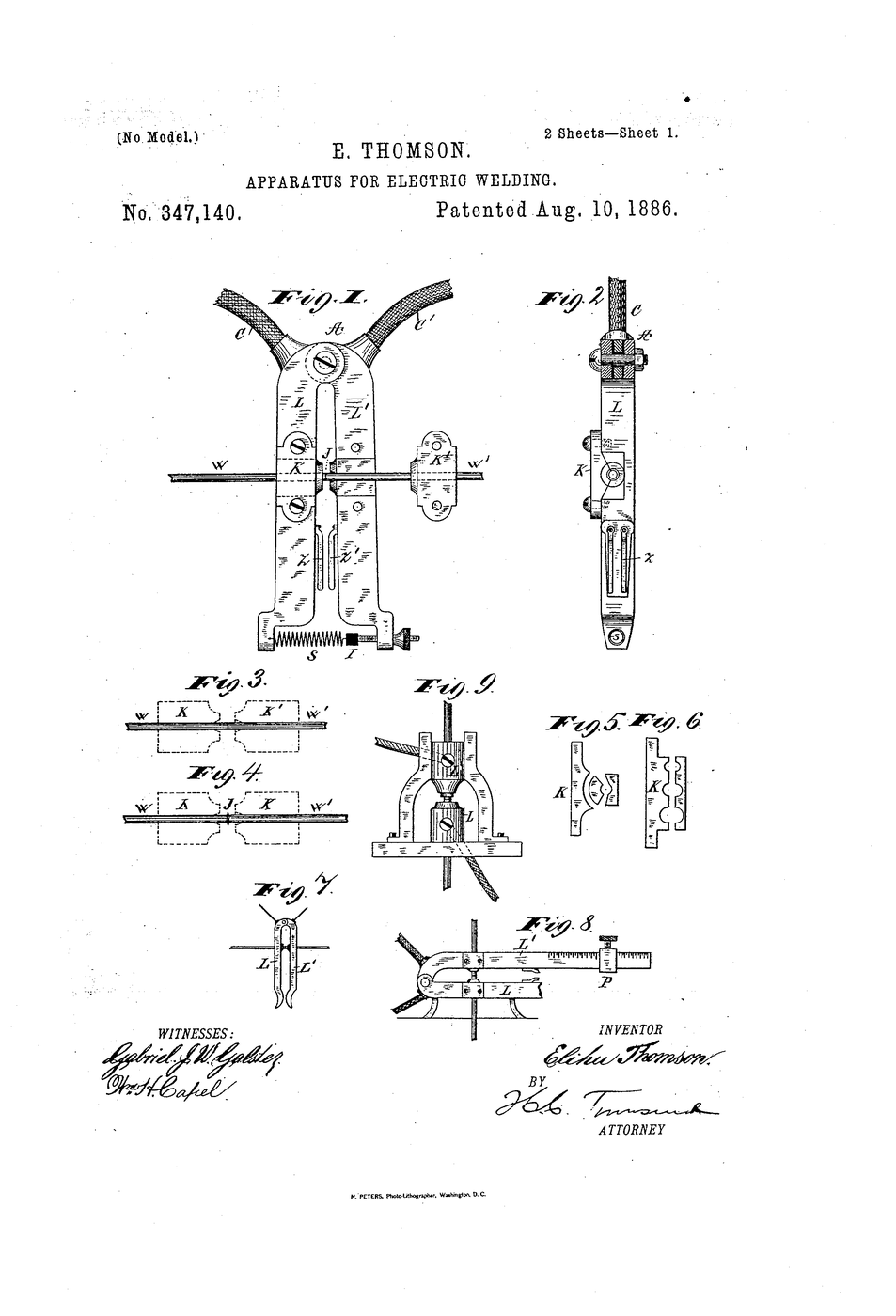
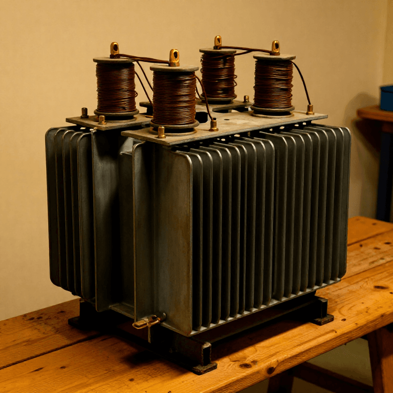
Elihu Thomson patented the apparatus as US 347,140, “Apparatus for Electric Welding”, granted 10 August 1886. The drawing shows two wires clamped end to end in a scissor-like holder, a transformer secondary of one heavy turn feeding them, and a spring that pushes the ends together as they soften. Thomson had noticed the effect while experimenting with a shorted transformer secondary: the short circuit did not simply waste power, it welded.
Why it mattered more than it looks. There is no filler metal, no flux, no shielding gas and no skill in the hand — the weld is set by current, time and force, three numbers a machine can hold better than a person. That is why resistance welding, not arc welding, is what actually assembles a car body: a modern shell carries several thousand spot welds, each made in well under a second by a robot repeating three numbers.
This blueprint uses a small battery spot welder to measure all three, and to prove the claim that the heat appears at the interface rather than in the electrodes.
Instructions
Write down the claim you are testing
Write down the claim you are testing
Record the question: when current passes through two touching pieces of metal, where does the heat appear? Predict an answer before measuring.
Read the resistances that make it work
Read the resistances that make it work
Measure the resistance along a single 50 mm strip of nickel, then across two strips laid one on the other. The contact reading is higher. That difference is the whole principle.
Tools needed:
 Analog Multimeter
 Steel Ruler (30cm)
Note why the reading is only indicative
Note why the reading is only indicative
A handheld meter cannot resolve sub-milliohm contact resistance accurately. Record it as a comparison, not an absolute — the ranking is what matters here.
Materials for this step:
 Graph Paper1 sheet
Set up the spot welder and safety
Set up the spot welder and safety
Set the welder on a non-flammable surface. Put on safety glasses. Molten metal can spit from the joint even at battery-welder power.
Tools needed:
 Battery Spot Welder
 Clear Safety Glasses
 Leather Gloves
Make a reference weld
Make a reference weld
Overlap two nickel strips by 5 mm. Weld at the welder's mid setting. Record the pulse duration the machine reports.
Materials for this step:
 Copper1 piece
Tools needed:
Battery Spot Welder Vernier Caliper
Measure the current
Measure the current
Clamp the current meter around one electrode lead and repeat the weld. Record the peak current in amperes.
Tools needed:
 Current Clamp Meter AC/DC 600ABattery Spot Welder
Vary the time, hold the current
Vary the time, hold the current
Make three welds at short, medium and long pulse settings, current unchanged. Label each coupon with the marker.
Materials for this step:
Copper3 piecesTools needed:
Battery Spot Welder Permanent Marker
Vary the electrode force, hold the rest
Vary the electrode force, hold the rest
Repeat three welds pressing lightly, normally and hard. Force changes contact resistance, so it changes the heat even at identical current.
Materials for this step:
Copper3 piecesTools needed:
Battery Spot WelderPermanent MarkerPull each weld apart and record the failure
Pull each weld apart and record the failure
Pull each coupon with the force meter until it fails. Record the peak force and whether the joint tore a plug of metal out or simply peeled.
Tools needed:
 Force Meter (Spring Scale)
 Bench Vise
Plot force against pulse time
Plot force against pulse time
Plot pull-apart force on the vertical axis, pulse time on the horizontal. Expect a rise, a plateau, then a fall as the joint is burned through.
Materials for this step:
Graph Paper1 sheetCheck where the heat actually went
Check where the heat actually went
Immediately after a weld, read the temperature of the joint and of the electrode tips. The joint is far hotter. That is the claim from step 1, confirmed.
Tools needed:
 Infrared Thermometer
Inspect the nugget under magnification
Inspect the nugget under magnification
Look at a torn joint under the magnifier. A sound weld shows a round recrystallised nugget; a cold one shows only flattened contact marks.
Tools needed:
 Magnifying Glass
Safety awareness — what this process does and does not risk
Safety awareness — what this process does and does not risk
No arc, so no arc-eye — resistance welding is one of the few electric welding processes with no significant ultraviolet output. The real risks are different: expelled molten metal from an overheated joint, which is why safety glasses are worn throughout, and burns from the workpiece, which stays hot long after it stops glowing.
The current is large but the voltage is very low, typically one or two volts across the electrodes, so shock is not the hazard people expect. The hazard is the energy source feeding it: a shorted lithium or lead-acid cell can deliver hundreds of amperes into a dropped tool. Keep the leads tidy and disconnect between sessions.
Tools needed:
Clear Safety GlassesHistory & Context
History & Context
US 347,140, “Apparatus for Electric Welding”, Elihu Thomson, granted 10 August 1886. The sheet is signed “Elihu Thomson” alone. Figures 3 and 4 show two wire ends before and after upsetting; the claims cover the clamping jaws, the single-turn secondary and the mechanism that maintains pressure as the metal softens.
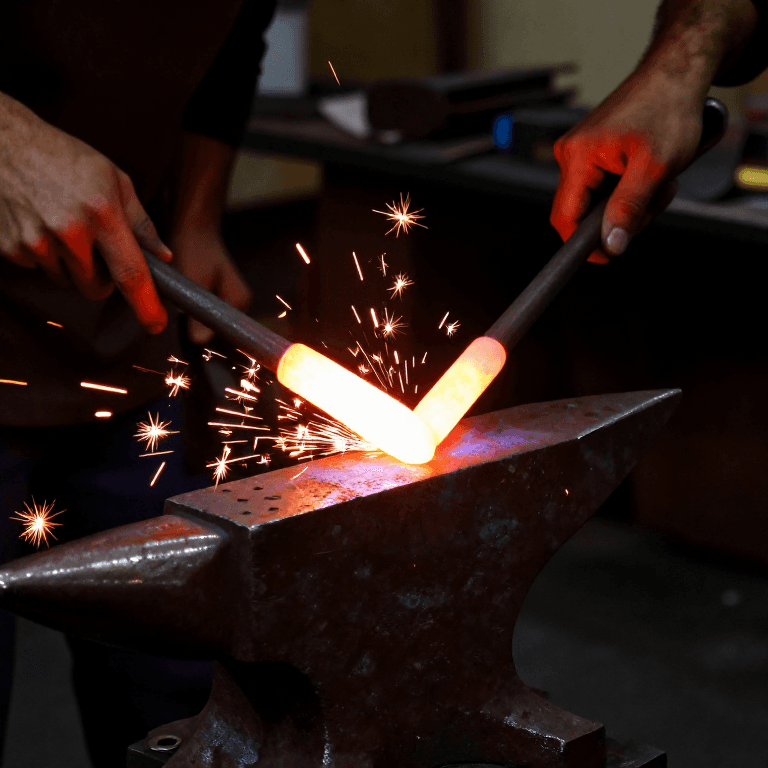
Thomson found it by accident, and said so. He was demonstrating induction with a transformer whose secondary was a single heavy loop. Shorting it did not blow anything up; it heated the joint white and fused it. The invention is the recognition, not the phenomenon — blacksmiths had been fusing metal by heat and pressure for three thousand years, and forge welding is the same physics with a fire instead of a current.
The three numbers. Everything in resistance welding reduces to current, time and electrode force. Joule heating gives Q = I²Rt, so heat rises with the square of current but only linearly with time — which is why the process is fast and why a small current increase matters far more than a long pulse. Force is the counter-intuitive one: pressing harder lowers contact resistance and therefore lowers heat, so more force is not more weld.
Where it went. Thomson's company merged into General Electric in 1892. Spot welding reached the motor industry in the 1930s and is now the dominant joining process in car manufacture by sheer count — a typical unibody carries between three and five thousand spot welds. Seam welding, projection welding and flash butt welding are all the same patent's physics with the geometry changed.
What it cannot do. Both sides must be reachable by an electrode, the sheets must be thin enough for the current to cross before the surroundings heat up, and highly conductive metals such as aluminium and copper are difficult precisely because they do not resist enough. That last limit is why the aircraft industry went to blind rivets instead — a problem the blind rivet solved in 1916.
Tools Required
12- Placeholder
- Placeholder
- Placeholder
- Placeholder
- Placeholder
- Placeholder
- Placeholder
- Placeholder
- Placeholder
- Placeholder
- Placeholder
- Placeholder
Connected Blueprint Materials

Related Blueprints
These blueprints share knowledge with this one — techniques, materials, or principles that connect them in the learning graph.

CC0 Public Domain
This blueprint is released under CC0. You are free to copy, modify, distribute, and use this work for any purpose, without asking permission.
Support the Maker by purchasing products through their Blueprint where they earn a Maker Commission set by Vendors, or create a new iteration of this Blueprint and include it as a connection in your own Blueprint to share revenue.