ART
BEAUTY & WELLNESS
CRAFT
CULTURE & HISTORY
ENTERTAINMENT
ENVIRONMENT
FOOD & DRINKS
REVERSE ENGINEERING
SCIENCES
SPORTS
TECHNOLOGY
WEARABLES
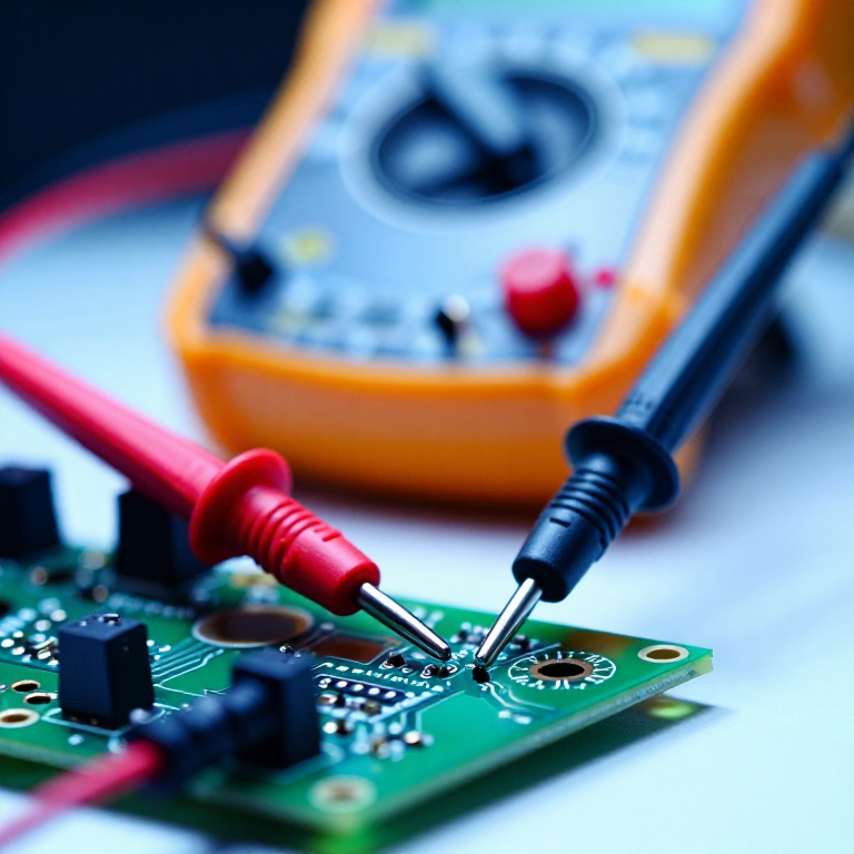


Using a Multimeter: Continuity, Volts, Ohms — and the Setting That Blows the Fuse
A multimeter answers three questions, and almost every fault you will ever chase is one of them. Is this connected? Is the voltage where it should be? Is this component the value it claims?
The meter is also the only instrument on the bench that can destroy itself through a normal-looking user error. There is one setting which, applied across a live supply, puts a dead short across it — and it is right next to the one you use constantly.
Learning the meter properly is the single highest-return hour a beginner can spend on electronics, because it converts 'it doesn't work' into a specific, findable fault.
Beginner
3 hours
Instructions
1
1
Continuity: the setting you will use most
Continuity: the setting you will use most
Set the meter to the diode/continuity symbol, touch the probes together and hear it beep. That beep means 'these two points are joined by a low resistance'.
Test the meter on itself before trusting a silence. A dead battery or a broken probe lead reads exactly like a broken circuit, and an afternoon has been lost to each of those more than once.
Use it with the power OFF. Continuity works by pushing a small current out of the meter and seeing what comes back, so a powered circuit gives nonsense readings and can injure the meter. Everything about continuity assumes a dead board.
Tools needed:
 Multimeter
2
2
Voltage is measured ACROSS, current THROUGH — and that is the whole trap
Voltage is measured ACROSS, current THROUGH — and that is the whole trap
For voltage, set volts DC and put the probes ACROSS the thing you are measuring, in parallel, while the circuit runs. Black on ground, red on the point of interest. The meter has a very high resistance so it barely disturbs anything.
For current the meter must go IN SERIES — the circuit is broken and the current made to flow through the meter, which now has a near-zero resistance. That is the danger: put a meter set to AMPS across a supply, as you would for volts, and you have connected a wire across it. The fuse blows if you are lucky.
Hence the habit: leave the meter on volts when you put it down, and move the red lead back from the amps socket immediately after a current measurement. Most blown meter fuses are the next measurement after a current one.
Tools needed:
Multimeter Bench Power Supply
3
3
Measure a resistor, and check it against its stripes
Measure a resistor, and check it against its stripes
Loading Jupyter Notebook...
Tools needed:
Multimeter Calculator
 Resistor Kit
4
4
Black lead on ground, and mind what 'ground' means
Black lead on ground, and mind what 'ground' means
Clip the black probe to the circuit's ground and leave it there, then move only the red probe. It halves the mistakes and frees a hand.
Every voltage is a DIFFERENCE between two points — there is no such thing as the voltage 'at' a node on its own. When a schematic says 5 V it means 5 V with respect to that circuit's ground, and if your black lead is somewhere else you are measuring something real but not what you meant.
This is also why two grounds must be joined before comparing readings between boards, and why measuring across a battery gives a number while measuring one terminal against a bench ground may not.
Tools needed:
Multimeter Breadboard
 Jumper Wires
5
5
Test a diode and an LED, and learn which way round they are
Test a diode and an LED, and learn which way round they are
On the diode setting, a silicon diode reads roughly 0.5 to 0.8 volts one way round and open the other. Reverse the probes and it should go silent.
That forward reading is the junction's forward voltage drop, and it tells you both that the part works and which way it is oriented — the red probe is on the anode when it reads. A diode that conducts both ways is shorted; one that conducts neither is open, and both are dead.
An LED does the same but at a higher voltage, and many meters will light it faintly on this setting, which is a satisfying way to sort an unmarked bag. Red LEDs read lowest, blue and white highest — a difference that matters when you size their resistor in the Ohm's law rung.
Tools needed:
Multimeter LED Kit
Tools Required
7- Placeholder
- Placeholder
- Placeholder
- 2 vendors sell this, none ship to you yetPlaceholder
- 1 vendor sell this, none ship to you yetPlaceholder
- 3 vendors sell this, none ship to you yetPlaceholder
- Placeholder
Related Blueprints
These blueprints share knowledge with this one — techniques, materials, or principles that connect them in the learning graph.
CC0 Public Domain
This blueprint is released under CC0. You are free to copy, modify, distribute, and use this work for any purpose, without asking permission.
Support the Maker by purchasing products through their Blueprint where they earn a Maker Commission set by Vendors, or create a new iteration of this Blueprint and include it as a connection in your own Blueprint to share revenue.