ART
BEAUTY & WELLNESS
CRAFT
CULTURE & HISTORY
ENTERTAINMENT
ENVIRONMENT
FOOD & DRINKS
REVERSE ENGINEERING
SCIENCES
SPORTS
TECHNOLOGY
WEARABLES
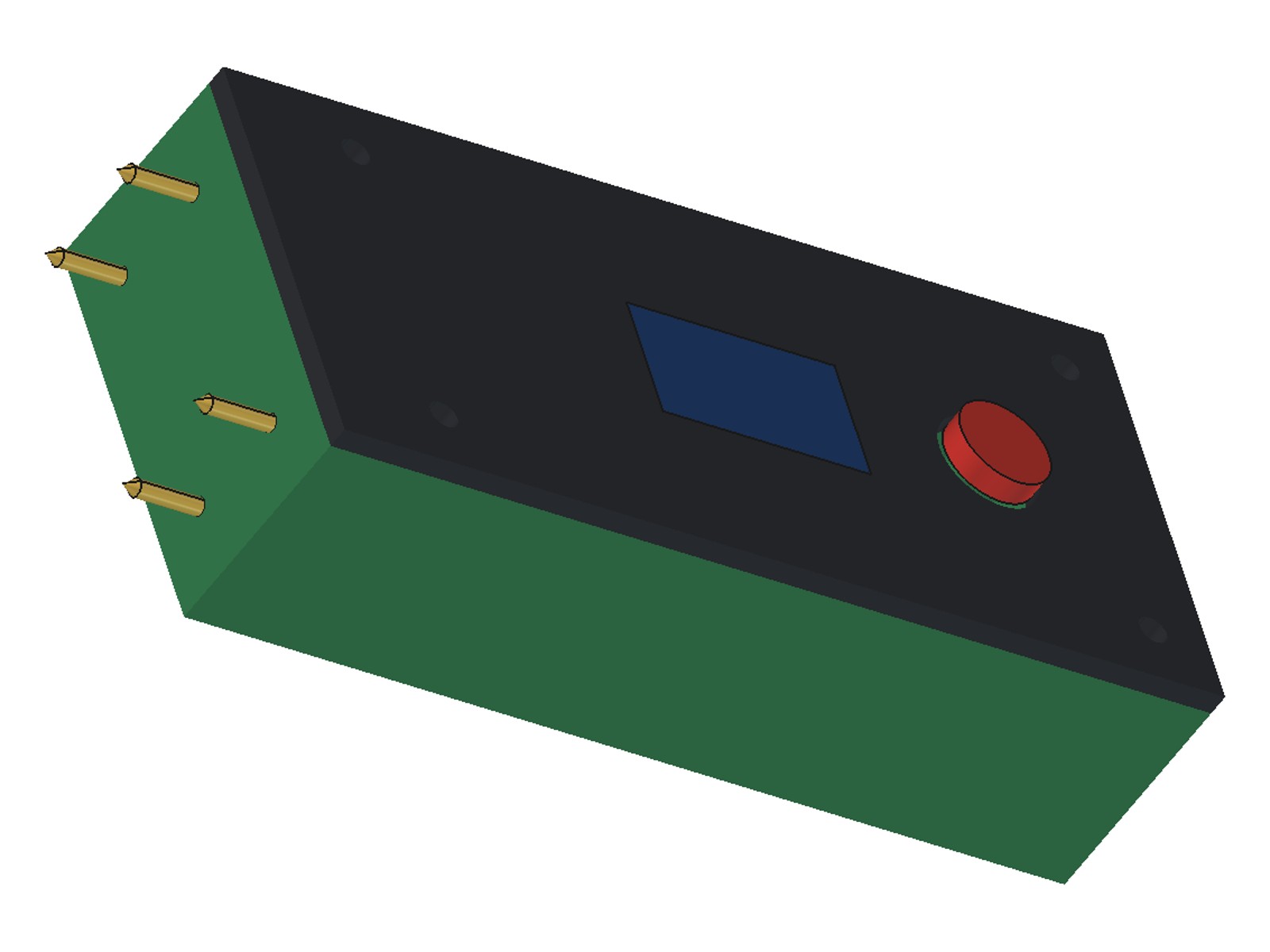
Wood Moisture Meter: Pins, a CMOS Timer and the Forest Products Laboratory Resistance Table (FPL-6)
Ed

Created by

Ed

22. November 2026FI
0
0
0
0
0

Wood Moisture Meter: Pins, a CMOS Timer and the Forest Products Laboratory Resistance Table (FPL-6)

A pocket pin meter that tells whether wood is dry enough to use, from 12 to 25 % moisture content. Four brass pins pushed into the wood make it the timing resistor of a CMOS timer; an ESP32 turns the frequency into resistance and reads the moisture from the US Forest Products Laboratory's own table for six woods, corrected for temperature.
Intermediate
About 1 day

Instructions

1

Watch a pin meter used

A pin-type meter checked on firewood and lumber (Wilson Forest Lands).
2

How wood resistance tells moisture

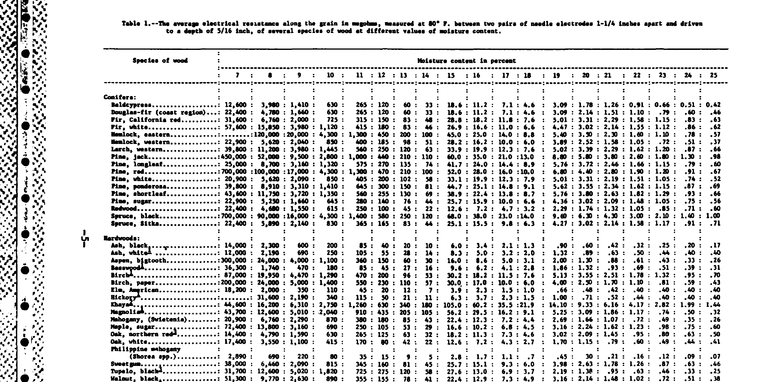
From FPL-6 (James, Forest Products Laboratory): below fiber saturation, wood's resistance rises steeply as it dries; Douglas-fir measures 22,400 megohms at 7 % and 0.46 megohm at 25 %. Above about 10 % it roughly halves for each 10 C rise. The meter reads the wettest wood touching both poles, so pins should reach 1/4 to 1/5 of the thickness, with the current along the grain.
Step 2 - Image 1
3

Resistance, frequency and temperature

Loading Jupyter Notebook...
4

Print the case

Floor down, no supports, PETG. The solid front block holds the four pins at the table's spacing.
Design FileSTLCC0 - Free

Materials for this step:

PETG FilamentPETG Filament45 g

Tools needed:

FDM 3D PrinterFDM 3D Printer
5

Print the lid

Flat, no supports. Windows for the OLED and the species button.
Design FileSTLCC0 - Free

Materials for this step:

PETG FilamentPETG Filament15 g

Tools needed:

FDM 3D PrinterFDM 3D Printer
6

Change the case (optional)

The FreeCAD script that made the case: OUT=. freecadcmd build_all.py
build_all.pypython
"""Batch 2531 -- printed case for the pin-type wood moisture meter. Pin spacing copies the FPL-6 Table 1 electrode (two poles 1-1/4 in =
31.75 mm apart, the two pins of each pole 1/2 in = 12.7 mm apart, driven 5/16 in = 8 mm deep). Other sizes ours. PETG, no supports.
  wm-base   tray 110 x 50 x 26 mm with a 10 mm solid pin block at the front end: four 1.9 mm holes for 2 mm brass pins (press fit +
            epoxy), USB slot at the back, 4 corner posts
  wm-lid    2.5 mm lid: OLED window 26 x 15 mm, 12.2 mm button hole, 4 x 3.4 mm holes
Run: OUT=<dir> freecadcmd build_all.py"""
import os
import FreeCAD as App, Part, MeshPart
OUT = os.environ["OUT"]; V = App.Vector
L, W, H, WALL, FLOOR, LID, BLOCK = 110.0, 50.0, 26.0, 2.4, 2.4, 2.5, 10.0
POLE, PAIR = 31.75, 12.7
def save(sh, n):
    sh = sh.removeSplitter(); bb = sh.BoundBox
    print(n, "valid", sh.isValid(), "solids", len(sh.Solids), "bbox", [round(v, 1) for v in (bb.XLength, bb.YLength, bb.ZLength)])
    MeshPart.meshFromShape(Shape=sh, LinearDeflection=0.03, AngularDeflection=0.12).write(os.path.join(OUT, n + ".stl"))
    return sh
POSTS = [(BLOCK + 4.5, WALL + 4.5), (L - WALL - 4.5, WALL + 4.5), (BLOCK + 4.5, W - WALL - 4.5), (L - WALL - 4.5, W - WALL - 4.5)]
base = Part.makeBox(L, W, H).cut(Part.makeBox(L - BLOCK - WALL, W - 2 * WALL, H, V(BLOCK, WALL, FLOOR)))
pins = []
for y in (W / 2 - POLE / 2, W / 2 + POLE / 2):
    for z in (H / 2 - PAIR / 2, H / 2 + PAIR / 2):
        pins.append((y, z))
        base = base.cut(Part.makeCylinder(0.95, BLOCK + 2, V(-1, y, z), V(1, 0, 0)))                      # pin hole through the block
        base = base.cut(Part.makeBox(4, 3, 3, V(BLOCK - 0.5, y - 1.5, z - 1.5)))                        # pocket behind for the wire joint
for x, y in POSTS:
    base = base.fuse(Part.makeCylinder(3.5, H - FLOOR, V(x, y, FLOOR))).cut(Part.makeCylinder(1.4, 14, V(x, y, H - 13)))
base = base.cut(Part.makeBox(WALL + 2, 12, 8, V(L - WALL - 1, W / 2 - 6, FLOOR + 3)))                   # USB slot
base = save(base, "wm-base")
lid = Part.makeBox(L, W, LID, V(0, 0, H))
lid = lid.cut(Part.makeBox(26, 15, LID + 2, V(45, W / 2 - 7.5, H - 1)))
lid = lid.cut(Part.makeCylinder(6.1, LID + 2, V(88, W / 2, H - 1)))
for x, y in POSTS:
    lid = lid.cut(Part.makeCylinder(1.7, LID + 2, V(x, y, H - 1)))
lid = save(lid, "wm-lid")
print("pins (y, z):", [(round(a, 2), round(b, 2)) for a, b in pins], "; poles", POLE, "mm apart, pins in a pole", PAIR, "mm apart")

Tools needed:

Digital Caliper 6-InchDigital Caliper 6-Inch
7

Fit the pins

Cut four 25 mm pieces of 2 mm brass rod and file one end of each to a point. Press them through the front block so 8 mm stands out, and fix them with epoxy. Inside, join the two pins of each pole with a short wire and solder; run one wire from each pole.

Materials for this step:

Brass RodBrass Rod1 piece (2 mm x 100 mm)
Two-Part EpoxyTwo-Part Epoxy2 g
Hookup WireHookup Wire0.3 m
Solder WireSolder Wire1 g

Tools needed:

HacksawHacksaw
Metal FileMetal File
Soldering IronSoldering Iron
8

Build the timer

On perfboard: ICM7555 powered from the ESP32's 3V3 and GND; pins 2 and 6 joined; 1 nF film capacitor from pins 2/6 to GND; pin 4 to 3V3. One pole wire to pin 3 (output), the other to pins 2/6. Pin 3 also to ESP32 GPIO27. OLED SDA 21, SCL 22; button GPIO26 to GND. Keep the pins 2/6 wiring short and clean the flux off: at 100 megohms, dirt leaks.

Materials for this step:
Integrated CircuitIntegrated Circuit1 piece (ICM7555 CMOS timer, 8-pin DIP)

Capacitor KitCapacitor Kit1 piece (1 nF film)
ESP32 Development BoardESP32 Development Board1 piece
OLED DisplayOLED Display1 piece (0.96 in, I2C)
Push ButtonPush Button1 piece (12 mm panel)
Perfboard / ProtoboardPerfboard / Protoboard1 piece
Hookup WireHookup Wire0.5 m
Solder WireSolder Wire2 g

Tools needed:

Soldering IronSoldering Iron
Wire StrippersWire Strippers
9

Load the firmware

Measure your 1 nF capacitor if you can and set C_TIMING; set WOOD_TEMP_C. Libraries Adafruit SSD1306 and GFX; board ESP32 Dev Module. The button steps through the six woods.
wood_moisture_meter.inocpp
// Pin-type wood moisture meter: the wood between two pairs of needles is the timing resistor of an ICM7555 CMOS timer
// (astable, one resistor from OUTPUT to THRESHOLD/TRIGGER, f = 1/(1.4 R C), Renesas ICM7555 datasheet EQ. 1); an ESP32 measures
// the period, works out R, corrects it to 80 F and reads moisture content from the USDA Forest Products Laboratory table
// (Gen. Tech. Rep. FPL-6, James 1975/1984, Table 1: megohms along the grain at 80 F, electrode of two pairs of needles
// 1-1/4 in apart driven 5/16 in deep). CC0. Pins (ours): timer OUTPUT -> GPIO27; OLED SDA 21, SCL 22; button GPIO26 to GND.
#include <Wire.h>
#include <Adafruit_GFX.h>
#include <Adafruit_SSD1306.h>
#include <math.h>

const int PIN_FREQ = 27, PIN_BTN = 26;
const float C_TIMING = 1.0e-9;      // 1 nF film capacitor: measure yours and put it here
const float WOOD_TEMP_C = 20.0;     // temperature of the wood (set yours); the table is for 80 F = 26.7 C

// Table 1 (FPL-6), megohms at 12 ... 25 percent moisture content
const int MC0 = 12, NMC = 14;
struct Species { const char* name; float r[NMC]; };
const Species SP[] = {
  {"Douglas-fir",   {120, 60, 33, 18.6, 11.2, 7.1, 4.6, 3.09, 2.14, 1.51, 1.10, .79, .60, .46}},
  {"Pine, white",   {200, 102, 58, 33.1, 19.9, 12.3, 7.9, 5.01, 3.31, 2.19, 1.51, 1.05, .74, .52}},
  {"Pine, ponder.", {300, 150, 81, 44.7, 25.1, 14.8, 9.1, 5.62, 3.55, 2.34, 1.62, 1.15, .87, .69}},
  {"Oak, red",      {125, 63, 32, 18.2, 11.3, 7.3, 4.6, 3.02, 2.09, 1.45, .95, .80, .63, .50}},
  {"Oak, white",    {80, 42, 22, 12.6, 7.2, 4.3, 2.7, 1.70, 1.15, .79, .60, .49, .44, .41}},
  {"Maple, sugar",  {105, 53, 29, 16.6, 10.2, 6.8, 4.5, 3.16, 2.24, 1.62, 1.23, .98, .75, .60}},
};
const int NSP = sizeof(SP) / sizeof(SP[0]);
int sp = 0;

Adafruit_SSD1306 oled(128, 64, &Wire, -1);
volatile unsigned long lastEdge = 0, period = 0;
void IRAM_ATTR onRise() { unsigned long t = micros(); period = t - lastEdge; lastEdge = t; }

// moisture content from megohms (at 80 F): log-log interpolation in the table; NAN outside 12-25 %
float mcFromMeg(float meg, const Species& s) {
  if (meg > s.r[0] || meg < s.r[NMC - 1]) return NAN;
  for (int i = 0; i < NMC - 1; i++) {
    if (meg <= s.r[i] && meg >= s.r[i + 1]) {
      float f = (log(meg) - log(s.r[i])) / (log(s.r[i + 1]) - log(s.r[i]));
      return MC0 + i + f;   // between i and i+1 percent (linear in log R, as the table steps are 1 percent)
    }
  }
  return NAN;
}

void show(const char* a, const char* b, const char* c) {
  oled.clearDisplay(); oled.setTextColor(SSD1306_WHITE);
  oled.setTextSize(1); oled.setCursor(0, 0); oled.print(a);
  oled.setTextSize(2); oled.setCursor(0, 22); oled.print(b);
  oled.setTextSize(1); oled.setCursor(0, 52); oled.print(c);
  oled.display();
}

void setup() {
  pinMode(PIN_FREQ, INPUT); pinMode(PIN_BTN, INPUT_PULLUP);
  attachInterrupt(digitalPinToInterrupt(PIN_FREQ), onRise, RISING);
  Wire.begin(21, 22); oled.begin(SSD1306_SWITCHCAPVCC, 0x3C);
}

void loop() {
  if (digitalRead(PIN_BTN) == LOW) { sp = (sp + 1) % NSP; delay(300); }
  noInterrupts(); unsigned long p = period, age = micros() - lastEdge; interrupts();
  char b[24], c[32];
  if (p == 0 || age > 3000000UL) {                    // no edge for 3 s: wood too dry (or no contact)
    show(SP[sp].name, "DRY <12%", "or pins not in the wood");
  } else {
    float f = 1e6 / p;
    float R = 1.0 / (1.4 * C_TIMING * f);              // ohms, EQ. 1
    float meg80 = R / 1e6 * pow(2.0, (WOOD_TEMP_C - 26.7) / 10.0);   // to 80 F: halves per +10 C (FPL-6, above 10 % MC)
    float mc = mcFromMeg(meg80, SP[sp]);
    snprintf(c, sizeof c, "R %.2f Mohm @ %.0fC", R / 1e6, WOOD_TEMP_C);
    if (isnan(mc)) snprintf(b, sizeof b, meg80 < SP[sp].r[NMC - 1] ? "WET >25%%" : "DRY <12%%");
    else snprintf(b, sizeof b, "%.1f %%", mc);
    show(SP[sp].name, b, c);
  }
  delay(250);
}

Materials for this step:

USB-C CableUSB-C Cable1 piece

Tools needed:

Computer with Arduino IDEComputer with Arduino IDE
10

Close it and check it

Fix the boards with tape, close the lid with 4 x M3 x 10. Check: a 1 megohm resistor across the poles must show R about 1 megohm; ten 10 megohm resistors in series, about 100. If 100 reads far off, your timer chip leaks more than typical.

Materials for this step:

Double-Sided TapeDouble-Sided Tape0.2 m
Socket Head Cap ScrewSocket Head Cap Screw4 piece (M3 x 10)

Tools needed:
Hex Key SetHex Key Set
Resistor KitResistor Kit
11

Measure wood

Choose the wood with the button. Push the pins in so the two poles lie one behind the other along the grain, 1/4 to 1/5 of the board's thickness deep, and read at once.
12

Troubleshooting

Meter problems and fixes.

Flow

Loading...
13

History and honest limits

From William L. James, Electric Moisture Meters for Wood, USDA Forest Service Gen. Tech. Rep. FPL-6 (1975): Table 1 values for six woods, the temperature rule and the electrode spacing. Timer figures from the ICM7555 datasheet. Ours: the circuit, the pins and case, the firmware. Range 12-25 % only; the temperature must be set by hand; the chip's leakage limits the dry end. Not built by us yet.

Materials

14

Tools Required

9

Design Files

2

CC0 Public Domain

This blueprint is released under CC0. You are free to copy, modify, distribute, and use this work for any purpose, without asking permission.

Support the Maker by purchasing products through their Blueprint where they earn a Maker Commission set by Vendors, or create a new iteration of this Blueprint and include it as a connection in your own Blueprint to share revenue.

Discussion

(0)

Log in to join the discussion

Loading comments...