NGHỆ THUẬT
LÀM ĐẸP VÀ SỨC KHỎE
THỦ CÔNG
VĂN HÓA VÀ LỊCH SỬ
GIẢI TRÍ
MÔI TRƯỜNG
THỰC PHẨM VÀ ĐỒ UỐNG
TƯƠNG LAI XANH
KỸ THUẬT NGƯỢC
KHOA HỌC
THỂ THAO
CÔNG NGHỆ
THIẾT BỊ ĐEO
Đã dịch
BLUEPRINT NFT

Nhấp nháy LED — Dự án Arduino đầu tiên của bạn
Dự án điện tử đầu tiên cổ điển! Xây dựng một mạch LED nhấp nháy bằng Arduino, breadboard, một điện trở và một LED. Hoàn hảo cho những người mới bắt đầu hoàn toàn — không cần焊接.
Hướng dẫn
1
1
Thu thập các thành phần của bạn
Thu thập các thành phần của bạn
Thu thập tất cả các thành phần được liệt kê dưới đây. Không cần h焊接 — mọi thứ đều cắm vào breadboard.
Vật liệu cho bước này:
 SparkFun Inventor's Kit - V3.21 bộ
Arduino Uno R31 cái
5mm LED (any color)1 cái
 220 ohm Resistor (1/4W)1 cái
Breadboard1 cái
Jumper Wires (Male-to-Male)2 cái
USB-B Cable1 cái
Công cụ cần thiết:
Computer with Arduino IDE
2
2
Sơ đồ mạch điện
Sơ đồ mạch điện
Tín hiệu chảy từ Arduino Pin 13 → điện trở 220Ω (R1) → LED (D1) → GND. Điện trở giới hạn dòng điện để bảo vệ LED.
Vật liệu cho bước này:
Arduino Uno R31 cái
5mm LED (any color)1 cái
220 ohm Resistor (1/4W)1 cái3
3
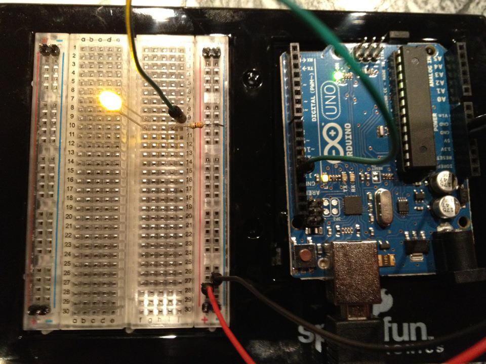
Kết Nối Dây
Kết Nối Dây
- Chèn LED vào breadboard — chân dài (anode +) ở một hàng, chân ngắn (cathode −) ở hàng tiếp theo.
- Chèn một chân của điện trở 220Ω vào cùng hàng với cathode của LED. Chân còn lại ở một hàng khác.
- Dây jumper từ hàng anode của LED → Arduino Pin 13.
- Dây jumper từ hàng còn trống của điện trở → Arduino GND.
Vật liệu cho bước này:
5mm LED (any color)1 cái
220 ohm Resistor (1/4W)1 cáiBreadboard1 cái
Jumper Wires (Male-to-Male)2 cái
4
4
Tải lên mã Blink
Tải lên mã Blink
Kết nối Arduino qua USB. Mở Arduino IDE, chọn Tools → Board → Arduino Uno, dán mã và nhấp Upload.
blink.inoarduino
Vật liệu cho bước này:
Arduino Uno R31 cái
USB-B Cable1 cái
Công cụ cần thiết:
Computer with Arduino IDE
5
5
PCB Bố cục (Tham khảo)
PCB Bố cục (Tham khảo)
Điều này hiển thị mạch dưới dạng bố cục PCB. Không cần thiết cho dự án này — breadboard hoạt động hoàn hảo — nhưng cho thấy mạch tương tự sẽ trông như thế nào nếu được sản xuất dưới dạng một bảng thực tế.
6
6
Kiểm tra và Thử nghiệm
Kiểm tra và Thử nghiệm
LED nhấp nháy? Chúc mừng! Bạn vừa lập trình phần cứng.
Khắc phục sự cố:
Các thử nghiệm tiếp theo:
Khắc phục sự cố:
- LED không sáng? Lật LED — chân dài hướng về Pin 13.
- LED luôn bật? Kiểm tra mã đã được tải lên thành công.
- Không có gì xảy ra? Xác minh dây nối khớp với sơ đồ mạch ở Bước 2.
Các thử nghiệm tiếp theo:
- Thay đổi giá trị
delay()để điều khiển tốc độ nhấp nháy - Thêm LED thứ hai trên Pin 12
- Thay thế bằng RGB LED (xem Mạch SIK 3)
Vật liệu
7- $105.00
- Tạm thời
Tổng ước tính
$105.00Related blueprints
Other builds that share materials, tools, or techniques with this one.

Using a Shift Register — SIK Circuit 14electronics/active
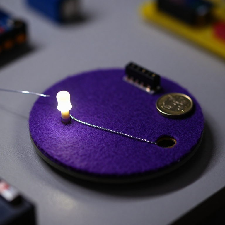
Blinking an LED with LilyPad Arduinoelectronics

Making Charcoal — The First Chemical Processmaterials
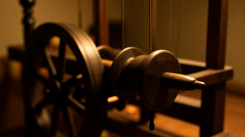
The Spinning Jenny — Multi-Spindle Yarn Productiontextiles
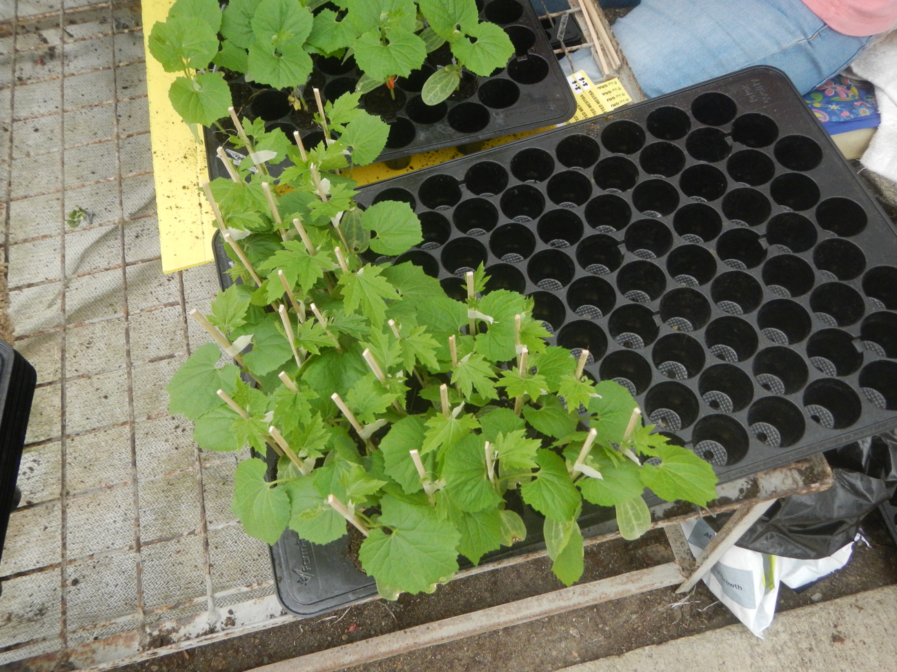
Starting Seeds Indoors — Raising Seedlings for a Head Start
Driving a Motor — SIK Circuit 12electronics/electromech
CC0 Phạm vi công cộng
Bản thiết kế này được phát hành theo CC0. Bạn tự do sao chép, sửa đổi, phân phối và sử dụng cho bất kỳ mục đích nào mà không cần xin phép.
Hỗ trợ nhà sáng tạo bằng cách mua sản phẩm qua bản thiết kế, nơi họ nhận Hoa hồng nhà sáng tạo do nhà bán hàng đặt, hoặc tạo phiên bản mới và kết nối trong bản thiết kế riêng để chia sẻ doanh thu.