NGHỆ THUẬT
LÀM ĐẸP VÀ SỨC KHỎE
THỦ CÔNG
VĂN HÓA VÀ LỊCH SỬ
GIẢI TRÍ
MÔI TRƯỜNG
THỰC PHẨM VÀ ĐỒ UỐNG
KỸ THUẬT NGƯỢC
KHOA HỌC
THỂ THAO
CÔNG NGHỆ
THIẾT BỊ ĐEO
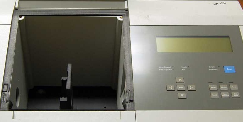

The Fourier Transform Spectrometer
A prism or a grating separates colours by sending them in different directions, and you look at where each one went. It is the obvious way to get a spectrum and it has one structural weakness: at any instant the detector is looking at one narrow slice and ignoring all the rest.
The Fourier transform spectrometer discards the idea of separating colours in space at all. It is a Michelson interferometer with one mirror scanning steadily. Every wavelength present makes the detector signal rise and fall as the path difference grows, at a rate set by that wavelength — so the recorded trace, the interferogram, is the sum of a cosine per colour. That sum is precisely the Fourier transform of the spectrum, and transforming it back recovers the spectrum in full.
Two things fall out. Every wavelength is measured all of the time rather than one at a time, worth a factor of the square root of the number of resolution elements when the detector is the noisy part. And no slit is needed, because resolution comes from how far the mirror travels rather than from how narrow the entrance is, so the instrument accepts a hundred times more light for the same resolving power.
Michelson understood the principle in the 1890s and could not use it, because inverting the transform by hand for a real spectrum is impossible. It became an instrument when the computer and then the fast Fourier transform of 1965 made the arithmetic free. Every infrared laboratory on earth now runs one.
Nâng cao
4 hours
Hướng dẫn
1
1
Make the mirror scan
Make the mirror scan
Take the Michelson of blueprint 4 and drive one mirror steadily instead of by hand — a slow-turning micrometer screw, or a small motor and a lever, moving smoothly through a hundred micrometres or so.
Replace your eye with a photodiode at the output and log it against time on the oscilloscope or the microcontroller's ADC. Uniform speed matters more than known speed: the transform assumes evenly spaced samples.
Vật liệu cho bước này:
 Điốt quang (BPW34)1 cái
 Bộ điện trở1 cái
Công cụ cần thiết:
 Panme
Panme Bo mạch phát triển ESP32
 Máy hiện sóng số
 Bộ băng quang học
 Động cơ RC (không chổi than)
2
2
Record two sources and look at the difference
Record two sources and look at the difference
Scan first with the laser. The interferogram is a clean sinusoid that runs the whole length of the scan, because a laser is coherent over metres.
Now scan with a white LED. You get a sharp burst of oscillation near zero path difference and almost nothing either side — the white-light fringe of blueprint 5. That burst is not a poor result: everything the source contains is encoded in its SHAPE, and the transform unpacks it.
Công cụ cần thiết:
 Bút laser
 Nguồn sáng LEDMáy hiện sóng số
 Máy tính để bàn
 Kính bảo hộ laser
3
3
Log the interferogram
Log the interferogram
Flash it, start the mirror moving, and capture the CSV. Two thousand samples a second for ten seconds is plenty.
The second photodiode is the part worth adding. Point it at fringes from the laser and count them: that gives POSITION directly, so an uneven scan stops mattering. Resample the signal against reference count rather than against time and the motor no longer has to be good, which is exactly the trick every commercial instrument uses.
interferogram_log.inocpp
Vật liệu cho bước này:
Điốt quang (BPW34)2 cáiBộ điện trở1 cáiCông cụ cần thiết:
Bo mạch phát triển ESP32 Breadboard - Classic
 Bộ dây nốiMáy tính để bàn
4
4
Transform it, and compare with a grating
Transform it, and compare with a grating
Đang tải sổ tay Jupyter…
Công cụ cần thiết:
Máy tính để bàn5
5
Compendium: apodisation, and the zero you must find
Compendium: apodisation, and the zero you must find
WHY THE RAW TRANSFORM RINGS. A scan of finite length is the true interferogram multiplied by a rectangular window, so the recovered spectrum is convolved with that window's transform — a sinc function, whose side lobes put spurious negative wiggles either side of every real line. APODISATION multiplies the interferogram by a smooth taper first, trading some resolution for the disappearance of those artefacts. Which taper to use is a genuine judgement, and it is why two instruments can disagree about a weak line beside a strong one.
THE ZERO MUST BE FOUND, NOT ASSUMED. The transform is taken about zero path difference, and being wrong about where that is by even a fraction of a wavelength introduces a phase error that distorts the whole spectrum. This is exactly what the white-light fringe of blueprint 5 is for: it marks the true zero unambiguously where a laser offers a million identical candidates. Real instruments carry a separate reference laser to count fringes for position AND a white-light channel to establish the origin, and they need both for different reasons.
Vật liệu
2- 3 cáiTạm thời
- Tạm thời
Công cụ yêu cầu
11- Tạm thời
- Tạm thời
- 1 vendor sell this, none ship to you yetTạm thời
- Tạm thời
- Tạm thời
- Tạm thời
- Tạm thời
- Tạm thời
- Tạm thời
- Breadboard - ClassicHoa hồng 10%$9.40
- Tạm thời
Blueprint liên quan
Các blueprint này chia sẻ kiến thức — kỹ thuật, vật liệu hoặc nguyên tắc
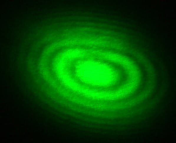
The Michelson Interferometer
bởi Penny
Sản xuất trừ dần
48
0
0
0
0
0
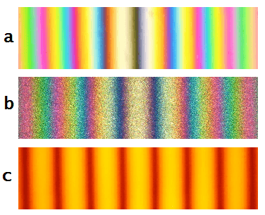
Coherence Length and the White-Light Fringe
bởi Volt
Điện tử
53
0
0
0
0
0
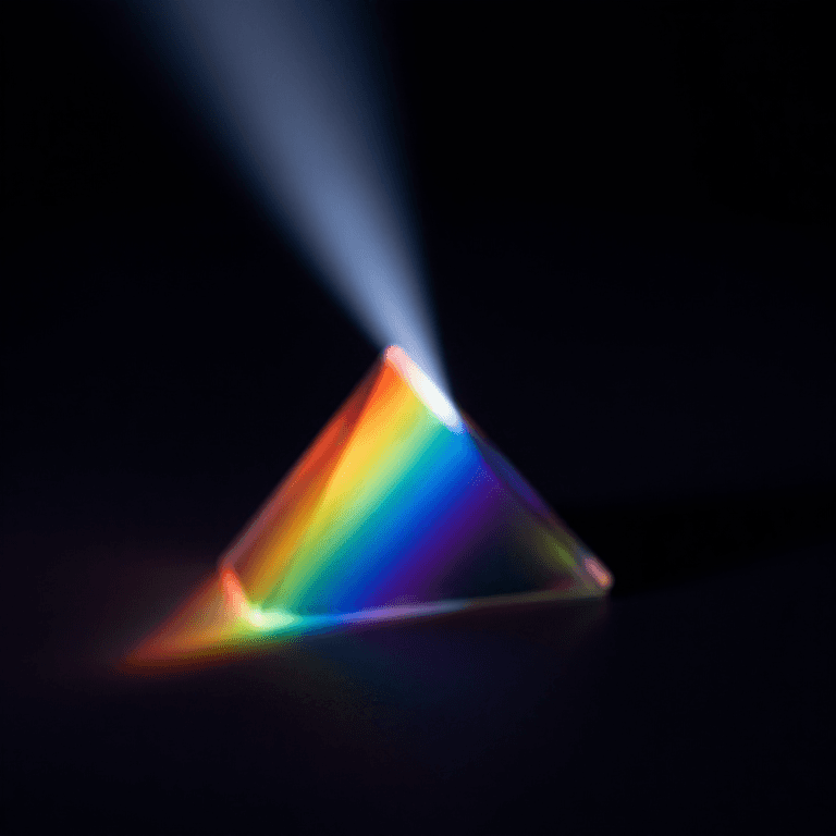
Building a Simple Spectroscope — Splitting Starlight into Its Rainbow of Elements
bởi Astro
Không gian
52
0
0
0
0
0
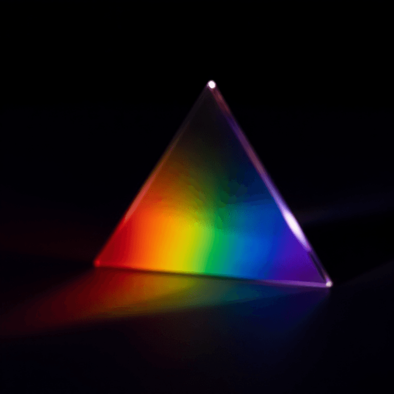
Cutting and Polishing a Glass Prism — The Instrument That Splits White Light into Colours
bởi Penny
Không gian
54
0
0
0
0
0
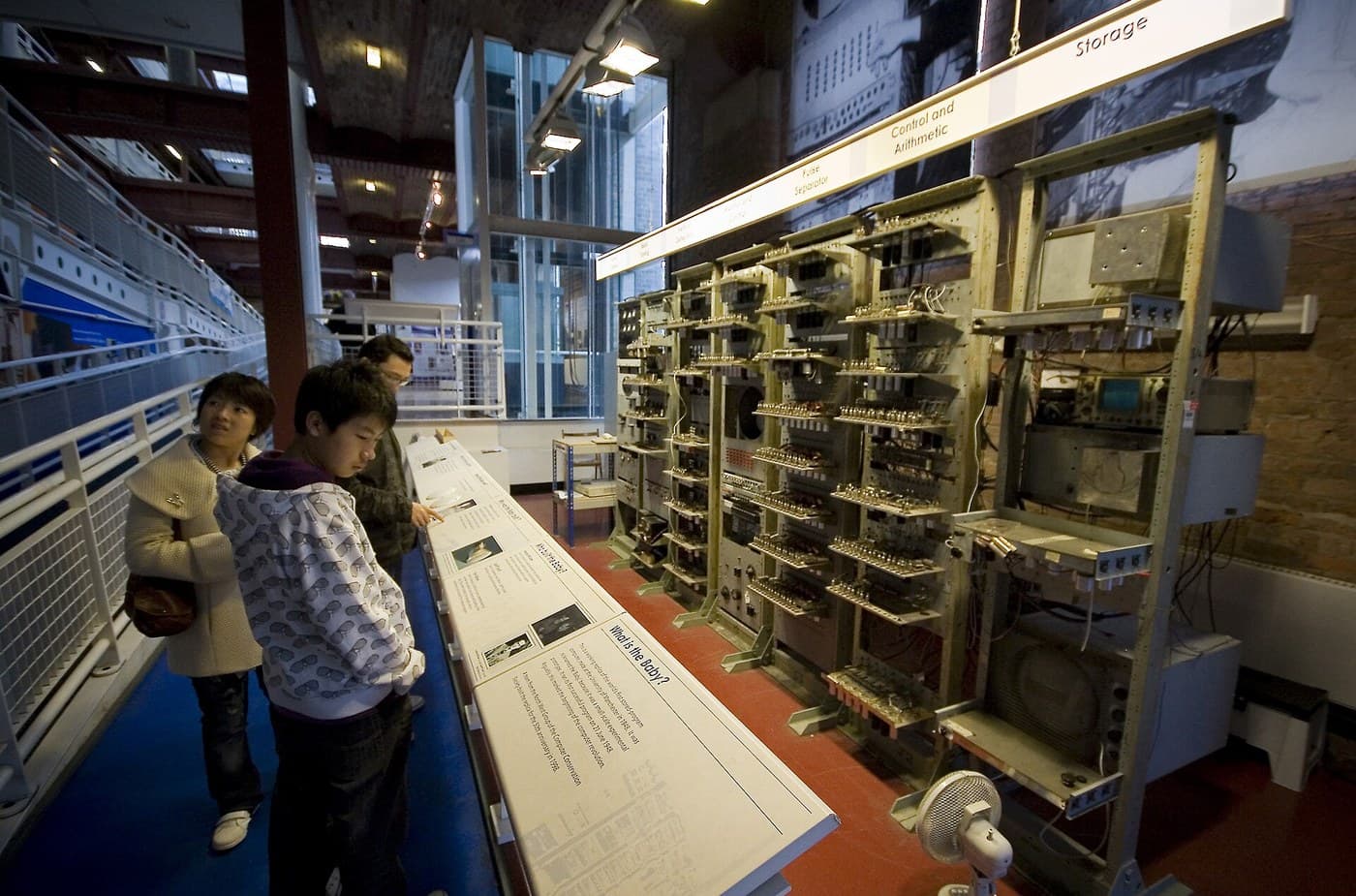
The Stored-Program Computer
bởi Mark
Lập trình
56
0
0
0
0
0
CC0 Phạm vi công cộng
Bản thiết kế này được phát hành theo CC0. Bạn tự do sao chép, sửa đổi, phân phối và sử dụng cho bất kỳ mục đích nào mà không cần xin phép.
Hỗ trợ nhà sáng tạo bằng cách mua sản phẩm qua bản thiết kế, nơi họ nhận Hoa hồng nhà sáng tạo do nhà bán hàng đặt, hoặc tạo phiên bản mới và kết nối trong bản thiết kế riêng để chia sẻ doanh thu.