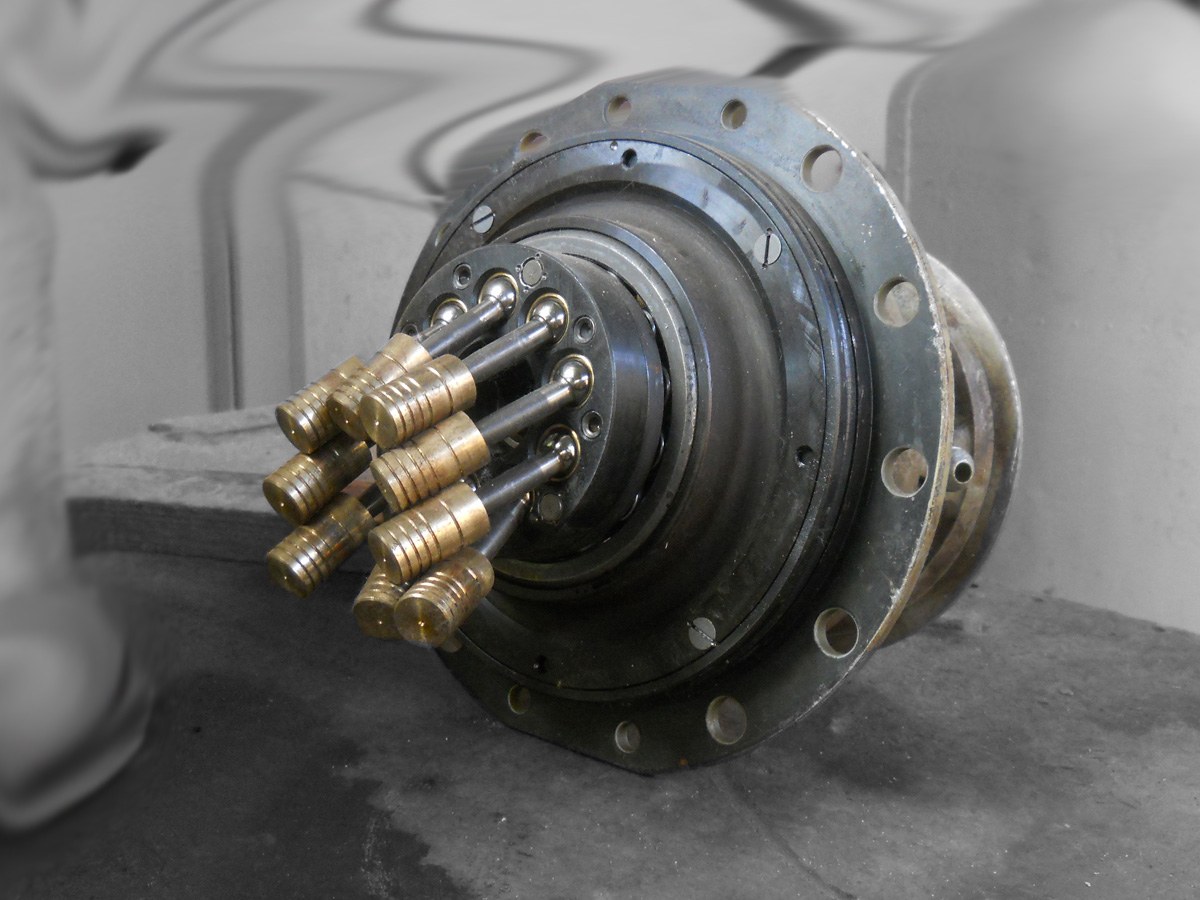


Variable-Displacement Axial-Piston Pump
Every pump so far in this batch delivers a fixed amount per revolution. To get less flow you slow the engine down; to reverse it you reverse the shaft. Both are things an engine is bad at.
Janney's pump makes displacement itself adjustable while the shaft runs at constant speed in one direction. Pistons sit in a rotating cylinder barrel, arranged in a ring parallel to the shaft — hence axial. Their outer ends bear on an inclined plate that does not rotate with them. As the barrel turns, each piston is forced to follow that incline: out on one half of the revolution, in on the other. The tilt angle is the stroke.
The geometry is one line: stroke = D × tan α, where D is the piston circle diameter and α the tilt. Everything follows from it. Tilt the plate further and each piston sweeps more. Bring it upright and the stroke goes to zero — the pump spins at full speed and delivers nothing. Tilt it the other way and the pistons still stroke, but now they draw where they used to deliver: the flow reverses while the shaft keeps turning the same way.
That is what makes a hydrostatic transmission possible. Infinitely variable speed, a true neutral, and reverse — all from one lever moving a plate, with no gears to change and nothing to disengage.
Reynold Janney, US 1,020,285, "Rotary Pump or Motor", filed 7 May 1910, granted 12 March 1912.
Hướng dẫn
Build the tilting-plate geometry before any fluid
Build the tilting-plate geometry before any fluid
Make a mechanical analogue: a disc that can be tilted to a measured angle, and a rod held against its face by a spring, parallel to the axis of rotation.
Rotate the disc slowly and watch the rod reciprocate.
Set the tilt to a measured angle. Measure the rod's total travel and the diameter of the circle its tip traces.
Check against stroke = D × tan α. Do this before adding pistons or fluid — if the geometry is not clear here, nothing downstream will be.
Vật liệu cho bước này:
 Dây thép lò xo1 m
Công cụ cần thiết:
 Thước cặp điện tử 6 inch
Plot stroke against angle and find where it is sensitive
Plot stroke against angle and find where it is sensitive
Measure the stroke at 5°, 10°, 15° and 20° and plot it.
Expect a curve that is very nearly a straight line at these angles, because tan α ≈ α in radians for small angles.
Now note what that means for a control: displacement is proportional to the lever position over the working range, so an operator's input maps predictably to speed. A mechanism whose control law is linear is one a human can drive.
Extend the calculation to 45° and see the curve begin to run away. Real pumps stop well short — typically 15–21° — and step 5 explains why.
Find zero, then go through it
Find zero, then go through it
Bring the plate upright — 0°. Rotate the disc at speed.
Expect the rod to stand completely still. Full shaft speed, zero stroke, zero flow.
Now tilt the plate the other way and rotate in the same direction as before. Watch when in the cycle the rod moves out versus in.
It has inverted. The port that was drawing is now delivering.
Those two observations together are the invention: a true neutral and a reversal, with the prime mover never changing speed or direction. No clutch, no gear train, no reverse idler.
Understand the port plate as a timing device
Understand the port plate as a timing device
Look at the flat plate the rotating barrel runs against. It carries two kidney-shaped slots — one inlet, one outlet — separated by solid lands at top and bottom dead centre.
Trace one cylinder through a full revolution and mark where its port is open to inlet, open to outlet, and open to neither.
The land matters more than the slots. A cylinder crossing from delivery to suction is still full of high-pressure fluid; if it is opened to the inlet instantly, that pressure dumps backwards as a shock — noise, vibration, and eventually cracked plates. So the land is made wide enough to seal, and given small relief notches to let pressure bleed away gradually.
This is a valve made of nothing but two holes and the geometry of rotation.
Find the thrust, which is the real engineering problem
Find the thrust, which is the real engineering problem
Load the rod against the tilted plate and feel the reaction where the two meet.
Resolve it: the plate pushes back along the piston, but because the face is inclined there is also a component sideways. Both grow with tilt angle, and both act on a joint that is sliding at full speed under full pressure.
That is why maximum tilt is limited to around 15–21°, and why so much of Janney's patent is about bearings — he specifies "two sets of anti-friction members interposed between the revoluble piston driving member and the tilting box or support", with conical rollers on flanged paths, precisely because the load direction shifts as the plate tilts.
The pumping is easy. Carrying the thrust from a sliding, rotating, angled contact is what took the invention from 1910 to reliability.
History & Context
History & Context
The patent. US 1,020,285, "Rotary Pump or Motor", Reynold Janney, filed 7 May 1910, granted 12 March 1912. The title's "or Motor" is not a hedge — it is the point. Drive the shaft and it pumps; force fluid in and it drives the shaft. A pair of these, one variable and one fixed, connected by two pipes, is a complete transmission.
Where it was actually used first. Janney's work went into production at the Waterbury Tool Company, and the early large-scale application was naval gun turret and steering gear — machinery that must be positioned smoothly and precisely at any speed, hold position under load, and reverse without shock. Mechanical gearing is poor at all three. His patent list from the same years runs through controlling apparatus for fluid gears, hydraulic controlling mechanism and speed-adjusting means, which is the shape of a man building a complete control system rather than one component.
The idea it made possible. A hydrostatic transmission has no gears to select, gives infinitely variable speed from standstill to maximum, reverses through neutral with one lever, and lets the engine sit at its best speed regardless of what the machine is doing. Combine harvesters, excavators, skid-steer loaders, zero-turn mowers and railway shunters all run on this. So does the swashplate compressor in most car air conditioning, working the same geometry backwards.
Two families, one principle. In a swashplate pump the inclined plate is fixed to the housing and only the barrel rotates; in a bent-axis pump the whole barrel is tilted relative to the drive shaft. Bent-axis reaches larger angles — around 40° — and so higher displacement per size, at the cost of a bulkier package. Both are Janney's geometry with the pivot in a different place.
Honest limitations. Efficiency falls away at small displacement, because internal leakage stays roughly constant while output shrinks — a hydrostatic drive crawling is a hydrostatic drive wasting most of its input as heat. The machines are expensive, need clean fluid, and are intolerant of contamination in a way a gear pump is not. And the fluid must be cooled: every point of inefficiency becomes heat in the oil, which is why these machines carry radiators of their own.
Vật liệu
1- Tạm thời
Công cụ yêu cầu
1- Tạm thời
Vật liệu bản thiết kế liên kết

Blueprint liên quan
Các blueprint này chia sẻ kiến thức — kỹ thuật, vật liệu hoặc nguyên tắc
CC0 Phạm vi công cộng
Bản thiết kế này được phát hành theo CC0. Bạn tự do sao chép, sửa đổi, phân phối và sử dụng cho bất kỳ mục đích nào mà không cần xin phép.
Hỗ trợ nhà sáng tạo bằng cách mua sản phẩm qua bản thiết kế, nơi họ nhận Hoa hồng nhà sáng tạo do nhà bán hàng đặt, hoặc tạo phiên bản mới và kết nối trong bản thiết kế riêng để chia sẻ doanh thu.