Driving an RGB LED — SIK Circuit 3
Hướng dẫn
Parts & Introduction
Parts & Introduction
An RGB LED contains three tiny LEDs (red, green, blue) in one package. By mixing different brightness levels of each color, you can create any color in the rainbow. This experiment introduces analogWrite() for PWM output.
Parts Needed
- 1x Arduino Uno + USB cable
- 1x Breadboard
- 1x RGB LED (Common Cathode)
- 3x 330Ω Resistors
- 5x Jumper Wires
RGB LED Pin Order (flat edge facing you): Red, Ground (longest pin), Green, Blue.
Vật liệu cho bước này:
 SparkFun Inventors Kit - V3.21 bộ
 RGB LED (Common Cathode)1 cái
 330 Ohm Resistor3 cái
 Jumper Wires5 cái
Công cụ cần thiết:
Hardware Hookup
Hardware Hookup
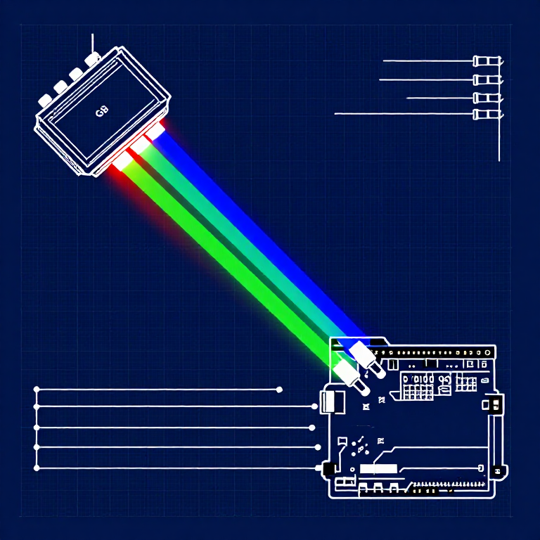
Wiring Instructions
- Place the RGB LED in the breadboard. Identify pins from the flattened edge: Red, GND (longest), Green, Blue.
- Connect the GND pin (longest, second from left) to the GND rail.
- Connect the Red pin through a 330Ω resistor to Arduino Pin 9.
- Connect the Green pin through a 330Ω resistor to Arduino Pin 10.
- Connect the Blue pin through a 330Ω resistor to Arduino Pin 11.
Pins 9, 10, and 11 are all PWM-capable (marked with ~ on the board).
Vật liệu cho bước này:
RGB LED (Common Cathode)1 cái330 Ohm Resistor3 cáiJumper Wires5 cáiArduino Code
Arduino Code
Open the Arduino IDE and upload the following sketch to your Arduino board.
Vật liệu cho bước này:
Công cụ cần thiết:
Test & Experiment
Test & Experiment
What You Should See
The LED cycles through 8 solid colors (off, red, green, blue, yellow, cyan, purple, white) for 1 second each, then smoothly fades through the entire color spectrum.
Troubleshooting
- Incorrect colors: With four pins close together, it's easy to misplace one. Double-check each connection.
- Red too bright: The red diode is often brighter. Try a higher-value resistor on the red pin, or reduce in code:
analogWrite(RED_PIN, redIntensity/3).
Experiments to Try
- Add a potentiometer to control which color is displayed.
- Create your own color sequences — try a "sunrise" effect (dark red → orange → yellow → white).
Vật liệu
6- $105.00
- Tạm thời
- $3.00
CC0 Phạm vi công cộng
Bản thiết kế này được phát hành theo CC0. Bạn tự do sao chép, sửa đổi, phân phối và sử dụng cho bất kỳ mục đích nào mà không cần xin phép.
Hỗ trợ nhà sáng tạo bằng cách mua sản phẩm qua bản thiết kế, nơi họ nhận Hoa hồng nhà sáng tạo do nhà bán hàng đặt, hoặc tạo phiên bản mới và kết nối trong bản thiết kế riêng để chia sẻ doanh thu.