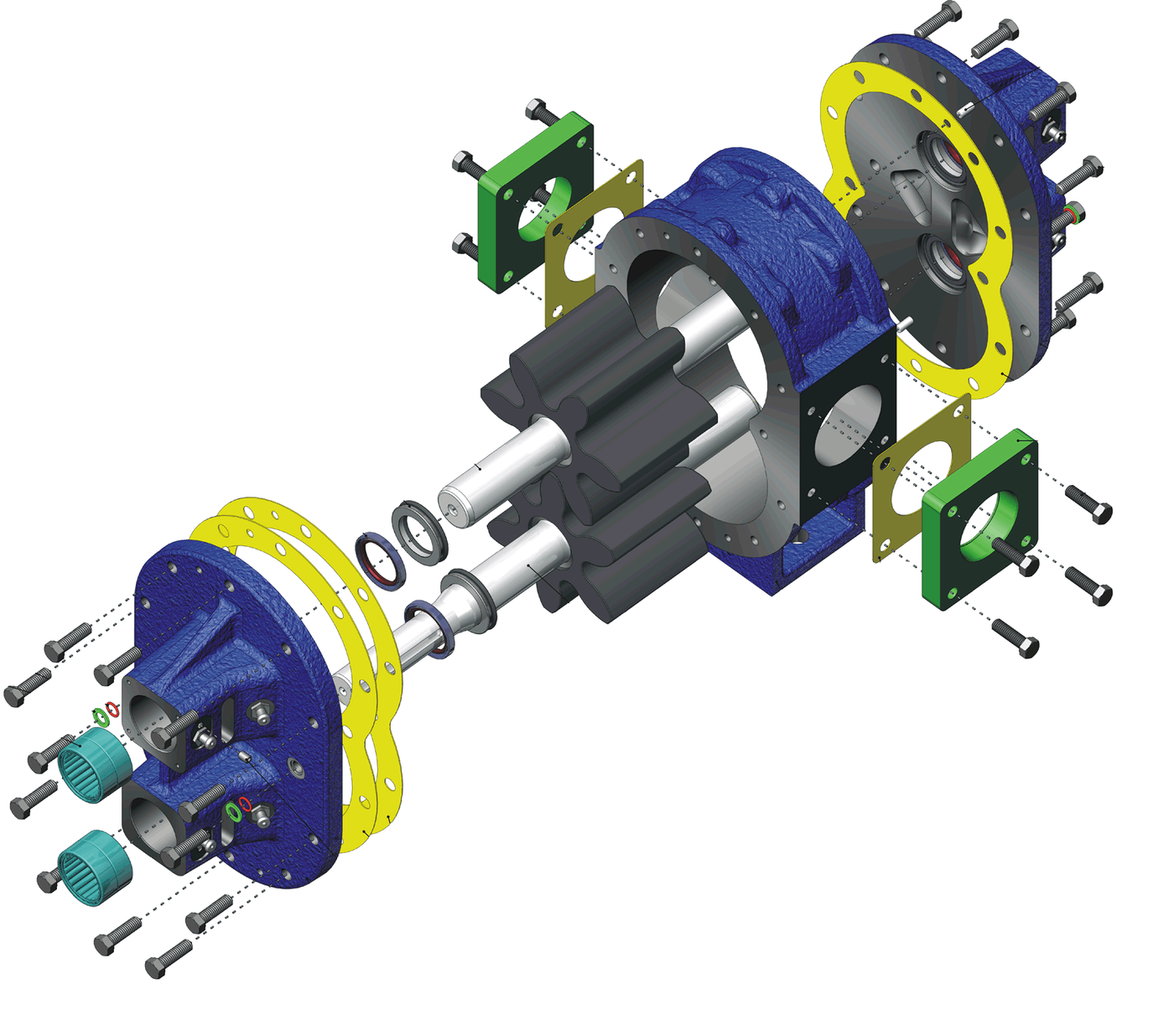


Gear Pump
A piston pump moves fluid in gulps. It has valves that slam, a stroke that stops and reverses, and a delivery that pulses. For a press that is fine. For anything that must be fed continuously — a lubrication system, a burner, a hydraulic circuit — it is a nuisance.
A gear pump has no valves and never stops. Two meshing gears turn inside a close-fitting housing. Where the teeth come out of mesh on the inlet side, space opens and fluid is drawn in. Each tooth space then carries its trapped charge around the outside, between the tooth and the housing wall, to the outlet. There the teeth go back into mesh, the space closes, and the fluid is pushed out.
The mesh itself is the seal. Fluid cannot take the short path back across the middle of the pump because the teeth are in contact there — which is why a gear pump needs no check valves at all.
It is positive displacement: a fixed volume per revolution, so flow follows speed and barely notices pressure. That is the opposite of a centrifugal pump, whose output collapses as back-pressure rises. The trade is that a gear pump will happily keep pumping into a blocked line until something bursts — which is why the next blueprint in this batch exists.
⚠ Attribution is genuinely contested. Johannes Kepler is credited with a gear pump around 1600–1604, a model of which was made by the Prague clockmaker Jost Bürgi in 1604. Gottfried Heinrich Graf zu Pappenheim is credited with a two-axis rotary pump in 1636. We state both; the mechanism is not in doubt.
Imiyalelo
Trace the path the fluid actually takes
Trace the path the fluid actually takes
Mesh two spur gears and turn them by hand, slowly.
Put a fingertip in a tooth space on the inlet side and follow that space all the way round.
It goes around the outside, against the housing wall — not through the middle. This surprises most people, and it is worth confirming physically before building anything.
Now look at the mesh point. The teeth are in contact, so there is no path back. The gears do two jobs at once: they carry the fluid, and they seal the return.
Izinto zokwakha zalesi sinyathelo:
 Isethi yamagiya aqondile (insimbi, amazinyo angu-20)2 izicucu
Build the housing, and understand why clearance is everything
Build the housing, and understand why clearance is everything
Make a housing that fits the gear pair closely at the tips and on both flat faces, with an inlet and an outlet port.
Measure the tip clearance and the end-face clearance with feeler gauges or by measuring parts with the caliper.
Aim for as little as will still turn freely.
Every gap is a leak path back from outlet to inlet — internal leakage, called slip. Unlike an external leak it makes no mess and no noise; it simply means the pump quietly delivers less than its geometry says it should, and more so as pressure rises.
Izinto zokwakha zalesi sinyathelo:
 Ipuleti Le-aluminium1 ucezu
 Izixhumanisi zethusi1 isethi
Amathuluzi adingekayo:
 I-Caliper Yedijithali Yamayintshi Ayi-6
 Insimbi yokuhlikihla izinsimbi
 Isibambo Sebhentshi
Prove it is positive displacement
Prove it is positive displacement
Turn the pump a counted number of revolutions and catch the delivery. Compute volume per revolution.
Now double the speed and measure again.
Expect the flow to double, and the volume per revolution to stay the same.
Then compare with a stirrer or impeller in the same fluid: spin it against a restriction and its output falls away. The gear pump does not care. Flow follows speed; pressure is whatever the system demands. That property is what makes gear pumps the standard for metering and lubrication — you can calculate delivery from shaft speed alone.
Amathuluzi adingekayo:
 Isikali Sedijithali Sasekhishini
 Uwoyela wamatshe ophephile ekudleni
Measure slip by raising the back-pressure
Measure slip by raising the back-pressure
Restrict the outlet progressively and measure the delivered flow at each setting, at constant speed.
Expect a line that is nearly flat but droops — and droops more steeply as pressure climbs.
That droop is slip, and it is why a gear pump's volumetric efficiency is quoted at a stated pressure rather than as one number.
Now warm the oil and repeat. Expect worse slip when hot, because thinner oil passes a given gap more easily. A pump that meters correctly cold can under-deliver at working temperature — which is a real calibration trap, not a curiosity.
Find the trapped volume between the teeth
Find the trapped volume between the teeth
Turn the gears very slowly and watch the space between two pairs of teeth as they come fully into mesh.
For a moment that space is closed off from both ports — sealed on all sides and shrinking.
Liquid does not compress. Expect a hard spot in the rotation, a squeak, or a jet escaping past the faces.
Real pumps cut small relief grooves into the housing side plates so that trapped pocket always has somewhere to go. Without them the pressure spike can exceed the working pressure of the pump, hammering bearings and shafts every single mesh, thousands of times a minute. It is a fault you find by listening, and the fix is two small slots.
History & Context
History & Context
Who invented it is genuinely unsettled. One line of evidence credits Johannes Kepler around 1600–1604 — better known for planetary orbits, but he designed a gear pump and had a working model built by the Prague clockmaker Jost Bürgi in 1604. It was described as an amusing little fountain throwing a jet of respectable height, and Kepler never found a commercial use for it. A second line credits Gottfried Heinrich Graf zu Pappenheim with a two-axis rotary capsule pump for air and water in 1636. We record both rather than choosing, because the record does not support choosing.
Kepler's failure is the interesting part. The mechanism was sound in 1604 and went essentially nowhere for two centuries. What it lacked was not the idea but the clearances of step 2 — you cannot make a gear pump that seals without the ability to cut accurate gears and bore a matching housing. It had to wait for the machine-tool trade that Maudslay and his successors built. A mechanism can be correct and still be too early.
Where it ended up. Gear pumps are almost certainly the most numerous hydraulic pumps ever made. One is running in nearly every internal combustion engine as the oil pump; others feed burners, lubricate machine tools, transfer paint, chocolate, resin and fuel, and supply the majority of mobile hydraulic circuits where variable displacement is not needed. They are cheap, compact, tolerant of contamination, and self-priming.
The internal-gear and gerotor variants. Put a smaller gear inside a ring gear with one more tooth, and the same principle runs much more quietly with less pulsation, in a shorter package. That is the gerotor, and it is what most modern engine oil pumps actually are — often driven straight off the crankshaft nose with no separate shaft at all.
Honest limitations, and the one that is dangerous. Displacement is fixed: the only way to vary flow is to vary speed, which is exactly the gap Janney's tilting plate filled. Abrasives destroy the clearances that make it work. And because it is positive displacement, it will keep pumping into a closed outlet until something fails — a hose, the housing, or the drive. A gear pump is never installed without a relief valve, and that is not a precaution but a requirement.
Izinto
3- Isibambeli
- 1 ucezuIsibambeli
- 1 isethiIsibambeli
Amathuluzi Adingekayo
5- Isibambeli
- Isibambeli
- Isibambeli
- Isibambeli
- Isibambeli
Izinto Zokwakha Ze-Blueprint Exhunyiwe
Ama-blueprint ahlobene
Lama-blueprint abelana ngolwazi — amasu, izinto noma izimiso

CC0 Isizinda Somphakathi
Le blueprint ikhishwe ngaphansi kwe-CC0. Ukhululekile ukukopisha, ukuguqula, ukusabalalisa, nokusebenzisa ngaphandle kwemvume.
Sekela uMenzi ngokuthenga imikhiqizo nge-Blueprint yabo IKhomishane Yomenzi kumiswe ngabathengisi, noma dala inguqulo entsha yale Blueprint bese uyifaka njengoxhumaniso ku-Blueprint yakho ukuze wabelane ngemali engenayo.