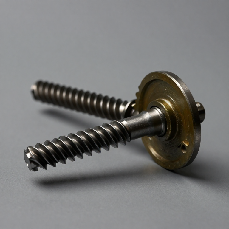


Worm Gear Reducer
A pair of spur gears reduces speed by the ratio of their tooth counts, so a 20:1 reduction needs a pinion and a wheel twenty times larger — or several stages stacked up. Either way it is bulky, and the input and output shafts stay parallel.
A worm drive gets a large ratio from two small parts. The worm is essentially a screw; the worm wheel is a gear cut to match it. One full turn of a single-start worm advances the wheel by exactly one tooth. So a 40-tooth wheel gives 40:1 in a single mesh, from parts of comparable size, with the shafts at right angles.
It has a second property that no ordinary gear pair has: it can be made self-locking. Drive the worm and the wheel turns. Try to drive the wheel and, if the lead angle is shallow enough, friction on the thread flank stops it dead — the load cannot back-drive the input. A hoist holds its load with the power off. A worm-driven gate stays shut when pushed.
That property is bought, not free. Self-locking requires a shallow lead angle, which means a lot of sliding rather than rolling contact. Worm drives are consequently the least efficient common gear type — often 50–70%, against 97–99% for a decent spur pair — and the rest becomes heat.
Imiyalelo
Count the ratio directly
Count the ratio directly
Mount a single-start worm meshing with a worm wheel. Count the wheel's teeth — say 40.
Mark both. Turn the worm exactly one revolution and check the wheel: it should have advanced exactly one tooth.
Ratio = wheel teeth / worm starts = 40/1 = 40:1. No arithmetic about pitch diameters — the ratio is a tooth count and a start count, nothing else.
Izinto zokwakha zalesi sinyathelo:
 Isethi yesikulufu esizungezayo nesondo salo (insimbi ne-bronze)1 ucezu
Amathuluzi adingekayo:
 Isibambo Sebhentshi
Try to drive it backwards
Try to drive it backwards
Now turn the wheel and try to make the worm rotate.
With a shallow-lead single-start worm, expect it not to move at all, however hard you push.
That is self-locking, and it is a friction effect, not a mechanical interlock — there is no catch or pawl anywhere in the assembly. It emerges from the thread angle alone.
Measure the lead angle that causes it
Measure the lead angle that causes it
Measure the worm's lead (axial advance per revolution) and its pitch diameter.
tan λ = lead / (π × pitch diameter)
Self-locking requires roughly tan λ < μ, the coefficient of friction — in practice a lead angle under about 5°.
Compute yours. If it is well under 5° it will self-lock; nearer 10° and it will back-drive. This is the whole design decision in one number.
Amathuluzi adingekayo:
 I-Caliper Yedijithali Yamayintshi Ayi-6
Find the heat
Find the heat
Run the drive under load for two minutes, then feel the housing near the mesh.
Expect it to be noticeably warm — much warmer than a spur gear pair doing the same work.
The worm thread slides along the wheel tooth rather than rolling across it, and sliding friction is the loss. Every degree of that heat is efficiency you paid for the self-locking.
Amathuluzi adingekayo:
 Ithemomitha Ye-Infrared
Look at what the wheel is made of
Look at what the wheel is made of
Note the materials: the worm is normally hardened steel, the wheel bronze.
That pairing is deliberate. Two hard surfaces sliding against each other under load gall and seize; a softer bronze wheel beds in to the steel worm, carries an oil film, and wears preferentially.
The wheel is designed to be the sacrificial part — cheaper to replace than the worm, and it protects the more expensive component. Same reasoning as the brass synchro ring in a gearbox.
History & Context
History & Context
Very old, and no single inventor. The worm and wheel is ancient — Archimedes is associated with the screw, and worm gearing appears in Hellenistic and Roman devices, in cotton gins, and throughout medieval and Renaissance machinery. Unlike the rest of this batch there is no foundational patent to cite, because the mechanism long predates the patent system. This blueprint therefore documents the principle rather than a claim, and does not manufacture an inventor for it.
Why it is in a power-transmission set anyway. Because it is the one common drive whose defining feature is a refusal to transmit — the only one specified for what it will not do.
Where the self-locking is the entire product. Hoists and winches that must hold a suspended load with no power and no brake. Machine-tool dividing heads. Gate and lift-bridge drives. The old worm-and-sector steering box, where self-locking meant road shocks did not come back through the wheel — and which was eventually abandoned precisely because drivers wanted some feedback.
The honest caution. Self-locking is a friction effect, so it degrades. Vibration can walk a self-locking worm drive backwards over time, because vibration momentarily reduces the effective friction. Anything holding a genuinely dangerous load — a passenger lift, a stage rig — carries a separate mechanical brake as well. Never treat self-locking as a safety device on its own.
Izinto
1- Isibambeli
Amathuluzi Adingekayo
3- Isibambeli
- Isibambeli
- Isibambeli
Izinto Zokwakha Ze-Blueprint Exhunyiwe
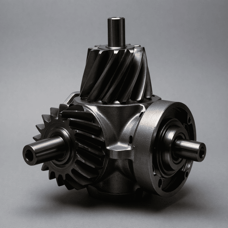
Ama-blueprint ahlobene
Lama-blueprint abelana ngolwazi — amasu, izinto noma izimiso

CC0 Isizinda Somphakathi
Le blueprint ikhishwe ngaphansi kwe-CC0. Ukhululekile ukukopisha, ukuguqula, ukusabalalisa, nokusebenzisa ngaphandle kwemvume.
Sekela uMenzi ngokuthenga imikhiqizo nge-Blueprint yabo IKhomishane Yomenzi kumiswe ngabathengisi, noma dala inguqulo entsha yale Blueprint bese uyifaka njengoxhumaniso ku-Blueprint yakho ukuze wabelane ngemali engenayo.