Colaboração
ARTE
BELEZA E BEM-ESTAR
ARTESANATO
CULTURA E HISTÓRIA
ENTRETENIMENTO
MEIO AMBIENTE
COMIDA E BEBIDAS
ENGENHARIA REVERSA
CIÊNCIAS
ESPORTES
TECNOLOGIA
TECNOLOGIA VESTÍVEL
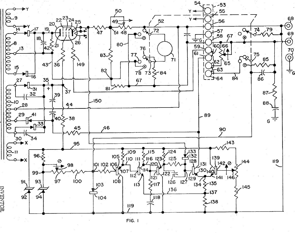


Bench Power Supply: Regulated, with Adjustable Current Limit and a Pentode Pass Tube (Gately, Forbro, US 3,243,690, 1966)
An adjustable bench supply that holds its output voltage steady and lets you set the most current it will deliver, so a circuit under test cannot be damaged. A pentode tube in series with the output is the regulator; a bridge with Zener references and a five-transistor amplifier keeps the output equal to the setting of one knob. A meter switch reads volts, amps, and the current limit, which can be set without disturbing the voltage.
Result: a regulated DC bench supply with adjustable current limiting.
Source: J. R. Gately (Forbro Design), US 3,243,690 (1966). Unknown: all component values and the output rating. Picture: the patent drawing.
Avançado
Unknown
Instruções
1
1
Wire the mains side
Wire the mains side
In a case, wire the power cord through a switch and a fuse to the primary of a transformer with four secondaries, and put a neon lamp across the primary to show the supply is on. One secondary (6.3 V) goes to two terminals for outside use, one heats the pentode, one is the main supply and one the bias supply. Ours: the case. Not given: the other winding voltages.
Materiais para este passo:
 Caixa de alumínio1 case
 Cabo flexível com ficha1 peça
 Interruptor de alavanca1 peça
 Fusível1 peça
 Transformador Abaixador1 four secondaries
 Lâmpada indicadora de néon1 peça
 Borne de painel2 6.3 V terminals
Ferramentas necessárias:
 Berbequim de mão
 Conjunto de chaves de fendas
2
2
Build the rectifiers
Build the rectifiers
Rectify the centre-tapped main winding with two rectifiers and smooth it with a capacitor. From the bias winding make two more supplies: one through two rectifiers with by-pass capacitors to a smoothing capacitor, for the pentode's screen and the reference circuit; the other through one rectifier and a capacitor, for the pentode's grid bias. Not given: the values.
Materiais para este passo:
 Díodo5 rectifiers
 Condensador eletrolítico3 smoothing
 Kit de condensadores1 by-pass
 Fio de solda1 as needed
Ferramentas necessárias:
 Ferro de soldar
3
3
Fit the pass tube and reference
Fit the pass tube and reference
Put the pentode in series with the positive output: plate to the main supply, cathode through two current-sensing resistors (one fixed, one adjustable) to the + output terminal; suppressor tied to the cathode, screen fed through a resistor. Build the reference: a Zener fed through a resistor feeds a second Zener at constant current, giving a fixed voltage. Against it set two resistors and the voltage-control variable resistor: the output voltage is proportional to that resistor's setting. Not given: the tube type and values.
Materiais para este passo:
 Válvula pêntodo1 series pass tube
 Díodo Zener2 peças
 Resistência1 conjunto
 Reóstato2 voltage control, current-limit rangeBorne de painel2 output + and -Fio de solda1 as needed
Ferramentas necessárias:
Ferro de soldar4
4
Build the error amplifier and current limit
Build the error amplifier and current limit
Build a five-transistor amplifier that drives the pentode's grid to keep the bridge balanced: a PNP emitter follower, an NPN stage, a PNP emitter follower with a resistor-capacitor roll-off against oscillation, a PNP driver whose base resistor has a capacitor across it for quick response, and an NPN clamp whose base is set by a potentiometer. Feed the voltage across the current-sensing resistors to the driver's base through a diode: above the limit it takes over and turns the pentode down. Choose the fixed sensing resistor to limit at about 125 % of rated current, trim with the potentiometer, and use the adjustable one to set lower limits. Not given: the transistor types and values.
Materiais para este passo:
 Transístor PNP3 peças
 Transístor NPN2 peçasDíodo1 peça
 Potenciómetro1 peçaKit de condensadores1 roll-off, speed-upResistência1 conjuntoFio de solda1 as needed
Ferramentas necessárias:
Ferro de soldar5
5
Fit the meter and use it
Fit the meter and use it
Fit a meter with a four-pole, three-position switch. Position 1 reads output volts through a multiplier resistor; position 2 reads current across a shunt in the negative line; position 3 (spring-return) puts a load resistor across the output and swaps a fixed resistor for the voltage control, so you can turn the limit control until the current limits at the value you want, without touching the voltage setting. Release the switch and use the supply.
Materiais para este passo:
 Instrumento de painel de bobina móvel1 peça
 Comutador rotativo1 4-pole, 3-positionResistência1 multiplier, shunt, load resistors
 Material desconhecido1 terminal strip
Ferramentas necessárias:
Ferro de soldarConjunto de chaves de fendasMateriais
21- 1 caseReferência
- 1 peçaReferência
- Referência
- 1 peçaReferência
- 1 four secondariesReferência
- Referência
- Referência
- 1 peçaReferência
- 3 smoothingReferência
- 1 roll-off, speed-upReferência
- 3 as neededReferência
- 1 series pass tubeReferência
- 2 peçasReferência
- 1 multiplier, shunt, load resistorsReferência
- 2 voltage control, current-limit rangeReferência
- 3 peçasReferência
- 2 peçasReferência
- Referência
- Referência
- 1 4-pole, 3-positionReferência
- 1 terminal stripReferência
Este projeto faz

CC0 Domínio Público
Este blueprint é liberado sob CC0. Você é livre para copiar, modificar, distribuir e usar este trabalho para qualquer finalidade, sem pedir permissão.
Apoie o Maker comprando produtos através do Blueprint, onde ele ganha uma Comissão Maker definida pelos vendedores, ou crie uma nova versão deste Blueprint e inclua-o como conexão no seu próprio Blueprint para compartilhar receita.