Colaboração
ARTE
BELEZA E BEM-ESTAR
ARTESANATO
CULTURA E HISTÓRIA
ENTRETENIMENTO
MEIO AMBIENTE
COMIDA E BEBIDAS
ENGENHARIA REVERSA
CIÊNCIAS
ESPORTES
TECNOLOGIA
TECNOLOGIA VESTÍVEL
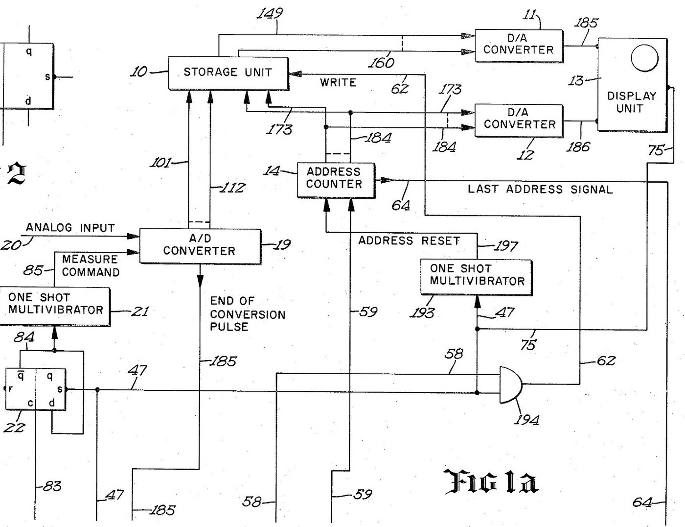


Digital Oscilloscope: Waveform Stored in Memory and Shown on a CRT (Schumann, Nicolet, US 3,816,815, 1974)
An oscilloscope with a memory. After a trigger, an analog-to-digital converter measures the input at regular intervals and writes each reading into its own memory register, replacing the old one. The screen then shows the memory: each register's number sets the beam's height, its address sets the beam's place across. The last waveform can be held on the screen as long as you like.
Result: a digital storage oscilloscope with 4,096 points of 12 bits, refresh and hold modes and single-shot capture.
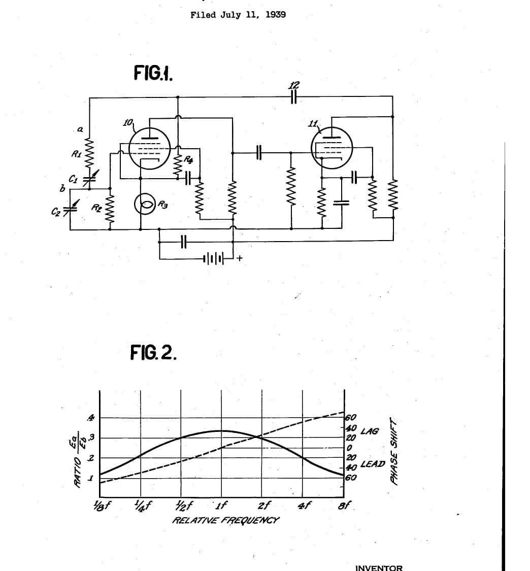
Source: R. W. Schumann (Nicolet), US 3,816,815 (1974). Unknown: sample rate, bandwidth, voltages and the parts used. Picture: the patent drawing.
Especialista
Unknown
Instruções
1
1
Sample and convert the input
Sample and convert the input
Bring the analog input to an analog-to-digital converter, through a BNC socket. A sampling oscillator, divided by four by two flip-flops so the first reading comes soon after the sweep starts, fires a one-shot multivibrator that gives the converter its measure command. The converter holds each 12-bit result on its output lines and signals the end of each conversion. Ours: a BNC socket. Not given: the sample rate.
Materiais para este passo:
 Conversor analógico-digital1 12-bit converter
 Oscilador de relógio1 sampling oscillator
 Sortido de circuitos integrados lógicos1 flip-flops, one-shots, gates
 Conjunto de conectores coaxiais (BNC / SO-239)1 input socket
Ferramentas necessárias:
 Ferro de soldar
 Descarnador de fios
2
2
Store each reading in memory
Store each reading in memory
Wire an integrated-circuit memory of 4,096 registers, 12 bits each, that can be read without changing it. A 12-bit address counter picks the register. On each write command the register at the current address takes the last reading from the converter, and the counter steps on. When the sweep starts, a one-shot resets the counter to zero. When it reaches the last address, its last-address signal ends the sweep.
Materiais para este passo:
 Memória de circuitos integrados1 4,096 x 12-bit store
Ferramentas necessárias:
Ferro de soldarDescarnador de fios3
3
Drive the CRT from the memory
Drive the CRT from the memory
Feed the addressed register's number to one digital-to-analog converter and the address to a second. Their outputs drive the vertical and horizontal deflection plates of a cathode-ray tube, so the beam always stands at the height of the stored reading and at the place of its address. Wire the sweep line to the tube's intensifier, to brighten the trace while a waveform is being taken.
Materiais para este passo:
 Conversor digital-analógico2 vertical and horizontal
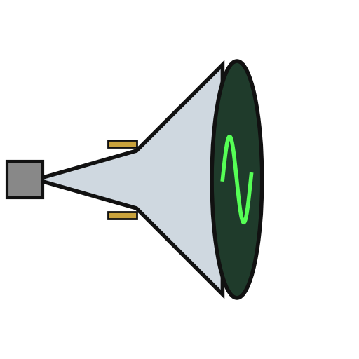 Tubo de raios catódicos1 display tube
Ferramentas necessárias:
Ferro de soldarDescarnador de fios4
4
Wire the trigger and the modes
Wire the trigger and the modes
A trigger input, usually from the leading edge of the input waveform, starts the sweep, once a measure flip-flop has armed it. Put a two-position mode switch on the face: MODE I and MODE II. Add a push button in the probe, a switch on the panel and an external initiate input; each goes through a flip-flop that removes contact bounce. Two more oscillators step the memory round to refresh the display between waveforms. Mount it all in a case with its supply. Ours: toggle switches, an aluminium case, a DC supply. Not given: the supply voltages.
Materiais para este passo:
Oscilador de relógio2 display sequencing oscillators Interruptor de alavanca2 mode and panel switches
 Botão de pressão1 probe switch
 Caixa de alumínio1 case
Ferramentas necessárias:
 Fonte de alimentação de corrente contínua
 Engenho de furarFerro de soldar
5
5
Capture and hold a waveform
Capture and hold a waveform
In MODE I, refresh: each new triggered waveform replaces the last on the screen. Press the probe or panel switch to hold: new waveforms are rejected and the last one stays on the screen. In MODE II the screen normally holds; on command, it takes the first waveform after the command, stores it and shows it steadily. Test it with a known signal.
Ferramentas necessárias:
 Gerador de funções
Materiais
10- 1 12-bit converterReferência
- 2 display sequencing oscillatorsReferência
- 1 flip-flops, one-shots, gatesReferência
- 1 input socketReferência
- 1 4,096 x 12-bit storeReferência
- 2 vertical and horizontalReferência
- 1 display tubeReferência
- Referência
- Referência
- 1 caseReferência
Ferramentas necessárias
5- 2 vendors sell this, none ship to you yetReferência
- Referência
- Referência
- Referência
Este projeto faz

Blueprints relacionados
Estes blueprints compartilham conhecimento — técnicas, materiais ou princípios
CC0 Domínio Público
Este blueprint é liberado sob CC0. Você é livre para copiar, modificar, distribuir e usar este trabalho para qualquer finalidade, sem pedir permissão.
Apoie o Maker comprando produtos através do Blueprint, onde ele ganha uma Comissão Maker definida pelos vendedores, ou crie uma nova versão deste Blueprint e inclua-o como conexão no seu próprio Blueprint para compartilhar receita.