Colaboração
ARTE
BELEZA E BEM-ESTAR
ARTESANATO
CULTURA E HISTÓRIA
ENTRETENIMENTO
MEIO AMBIENTE
COMIDA E BEBIDAS
ENGENHARIA REVERSA
CIÊNCIAS
ESPORTES
TECNOLOGIA
TECNOLOGIA VESTÍVEL
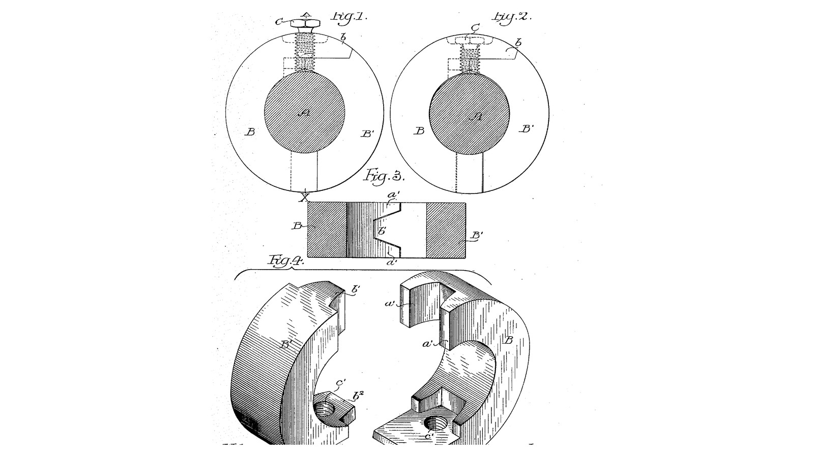


One-Screw Two-Part Shaft Collar: Hooked Ends Reach Round the Shaft So the Halves Cannot Open (Grundy, 1907)
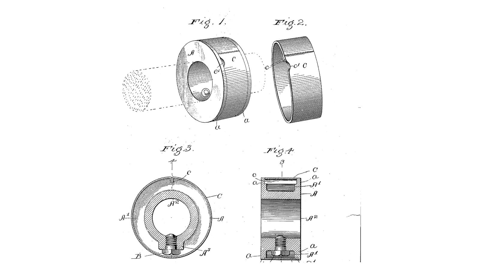
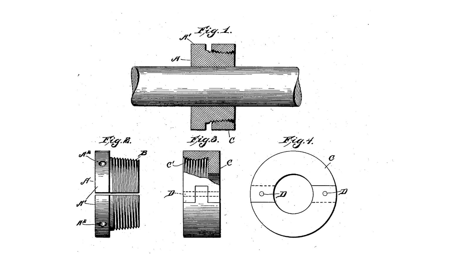
John R. Grundy of Philadelphia received US 860,369, dated 16 July 1907, for a two-part collar held by a single screw, where earlier split collars needed two. The screw passes through one pair of ends, an overhang on one part lying over the other. At the opposite side a tongue on one part fits a recess in the other. Both of those ends reach round the shaft past the diameter under the screw. When the screw's point presses the shaft, they hook under it and cannot open. Each part goes onto the shaft from the side, so the shaft stays in its bearings.
We cut the two parts from a turned brass ring with a piercing saw, from a full-size template. The patent gives no sizes; every size here is ours.
Avançado
About 2 days
Instruções
1
1
Why the hooks hold
Why the hooks hold
A carregar o notebook Jupyter…
2
2
Read US 860,369
Read US 860,369
"It is obvious that by using the single screw in place of a plurality of screws, as has hitherto been considered necessary, I am enabled to reduce the cost of the collar."
"The parts of said collar are placed in position on the shaft by being moved toward it in radial planes."
3
3
Turn the ring
Turn the ring
Grip 45 mm brass round bar in the 3-jaw chuck. Face it, turn it to 40 mm for 20 mm, centre-drill, drill through 15 mm and ream 16 mm. Part off 16 mm long and face the parted side.
Materiais para este passo:
 Barra redonda de latão1 peça
Ferramentas necessárias:
 Torno mecânico
 Placa de torno de 3 castanhas
 Ferramenta de corte para torno
 Conjunto de brocas de centrar
 Jogo de brocas
 Alargador
 Goiva de sangrar
 Paquímetro digital de 6 polegadas
 Óculos de segurança
4
4
Print the cutting template
Print the cutting template
Full-size A4 template: the end view of the ring with the outlines of parts B and B', and the bottom of the ring seen from below with the tongue b' and cheeks a'. Print at 100 %; its 50 mm bar must measure 50 mm.
5
5
Cut the parts apart
Cut the parts apart
Glue the end view on one end face of the ring, centred, and the strip on the outside at the bottom. Wax the blade. Top joint: hold the ring in soft jaws, face up, and saw with the blade along the axis: in from the outside 5 mm left of the line to 14 mm radius, round the 14 mm circle to the line, and down the line into the bore. Bottom joint: turn the ring over and saw with the blade across the wall, following the strip from one end face to the other: the cheeks a' 3 mm left of the line, the tongue b' 3 mm right of it. Go slowly at the corners; the two parts come apart.
Ferramentas necessárias:
 Impressora de jato de tinta
 Cola
 Torno de bancada
 Mordentes macios para torno
 Serra de joalheiro
 Cera de abelha
6
6
Fit the joints and cut away the bores
Fit the joints and cut away the bores
File the saw marks off the joints until the tongue slides into its recess and the overhang lies on the other part, with the two parts round a 16 mm bar. File each part's bore out to 18 mm across over the 22 degrees next to the top joint on its own side, B' to the left of the line and B to the right, as the template shows. Try them on the bar: put B on from below right, then B' from below left, sliding it up under the overhang and the tongue into its recess. File until each goes on without forcing.
Ferramentas necessárias:
 Barra redonda de aço macioTorno de bancadaMordentes macios para torno
 Jogo de limas
 Jogo de limas de agulhaPaquímetro digital de 6 polegadas
7
7
Drill and tap for the screw
Drill and tap for the screw
With both parts on the bar, the overhang lying on B', clamp the bar in the machine vice so the dashed screw line on the template stands upright. Drill 4.2 mm through the overhang and through B' into the bore, and tap M5 through both with cutting oil. Take the parts off and deburr the bore.
Materiais para este passo:
 Óleo de corte1 peça
Ferramentas necessárias:
Barra redonda de aço macio Engenho de furar
 Morsa de máquinaJogo de brocas
 Jogo de machos e cossinetes
 Desandador de machos
 Rebarbador manual
8
8
The collar in 3D
The collar in 3D
FreeCAD model, our sizes: parts B and B' on a 16 mm shaft, the overhang b and the M5 screw at the top, the tongue b' between the cheeks a' at the bottom, and the bores cut away beside the top joint.
9
9
Fit it on the shaft
Fit it on the shaft
Run an M5 x 12 cup point set screw into the overhang until it just shows. Put B onto the shaft from the side where the collar is wanted, then B' from the other side, its top under the overhang and its tongue into the recess. Tighten the screw with the hex key: it pushes on the shaft and draws both bottom ends down against it. Try to slide and turn the collar; it must not move.
Materiais para este passo:
 Parafuso sem cabeça de ponta côncava1 peça
Ferramentas necessárias:
 Jogo de chaves Allen
10
10
Troubleshooting
Troubleshooting
Grundy collar troubleshooting.
Flow
Loading...
11
11
History and honest limits
History and honest limits
**John R. Grundy** of Philadelphia, US 860,369, dated 16 July 1907, filed 28 January 1907. He claimed "a shaft collar made in two parts, and means for holding the parts together comprising a single screw passing through two adjacent ends of said two parts, the other ends of said parts being formed to co-act with the shaft to prevent their separation". His screw end also has a second projection b2 in a recess, holding the parts in line along the shaft; ours leaves it out, as the screw through both parts does that. His screw has a hex head; ours is a socket set screw. He gives no material; ours is brass, which a piercing saw cuts well. The patent gives no sizes; every size here is ours.
Materiais
3- 1 peçaReferência
- 1 peçaReferência
- Referência
Ferramentas necessárias
24- Referência
- Referência
- Referência
- Referência
- Referência
- Referência
- Referência
- Referência
- Referência
- Referência
- Referência
- Referência
- Referência
- Referência
- Referência
- Referência
- Referência
- Referência
- Referência
- Referência
- Referência
- Referência
- Referência
- Referência
Ficheiros de design
2Este projeto faz
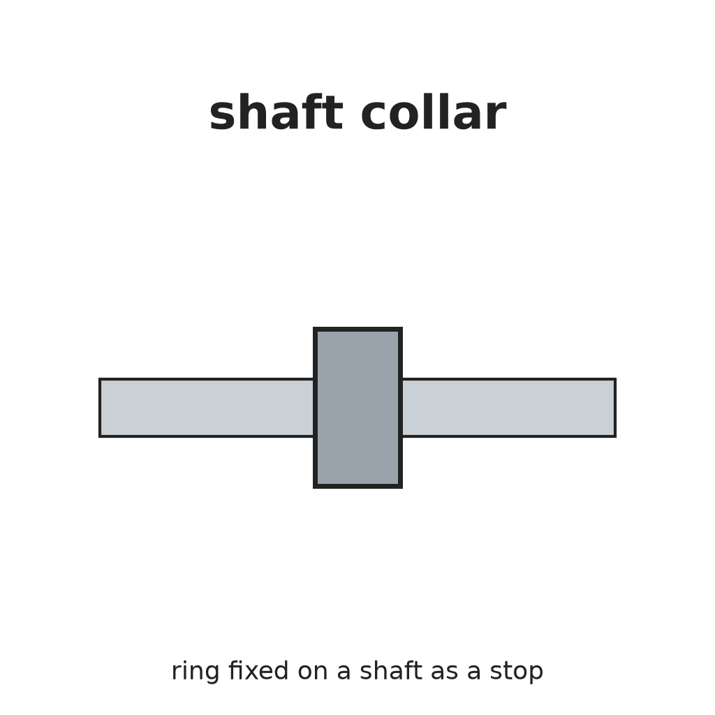
Blueprints relacionados
Estes blueprints compartilham conhecimento — técnicas, materiais ou princípios
CC0 Domínio Público
Este blueprint é liberado sob CC0. Você é livre para copiar, modificar, distribuir e usar este trabalho para qualquer finalidade, sem pedir permissão.
Apoie o Maker comprando produtos através do Blueprint, onde ele ganha uma Comissão Maker definida pelos vendedores, ou crie uma nova versão deste Blueprint e inclua-o como conexão no seu próprio Blueprint para compartilhar receita.