Colaboração
ARTE
BELEZA E BEM-ESTAR
ARTESANATO
CULTURA E HISTÓRIA
ENTRETENIMENTO
MEIO AMBIENTE
COMIDA E BEBIDAS
ENGENHARIA REVERSA
CIÊNCIAS
ESPORTES
TECNOLOGIA
TECNOLOGIA VESTÍVEL
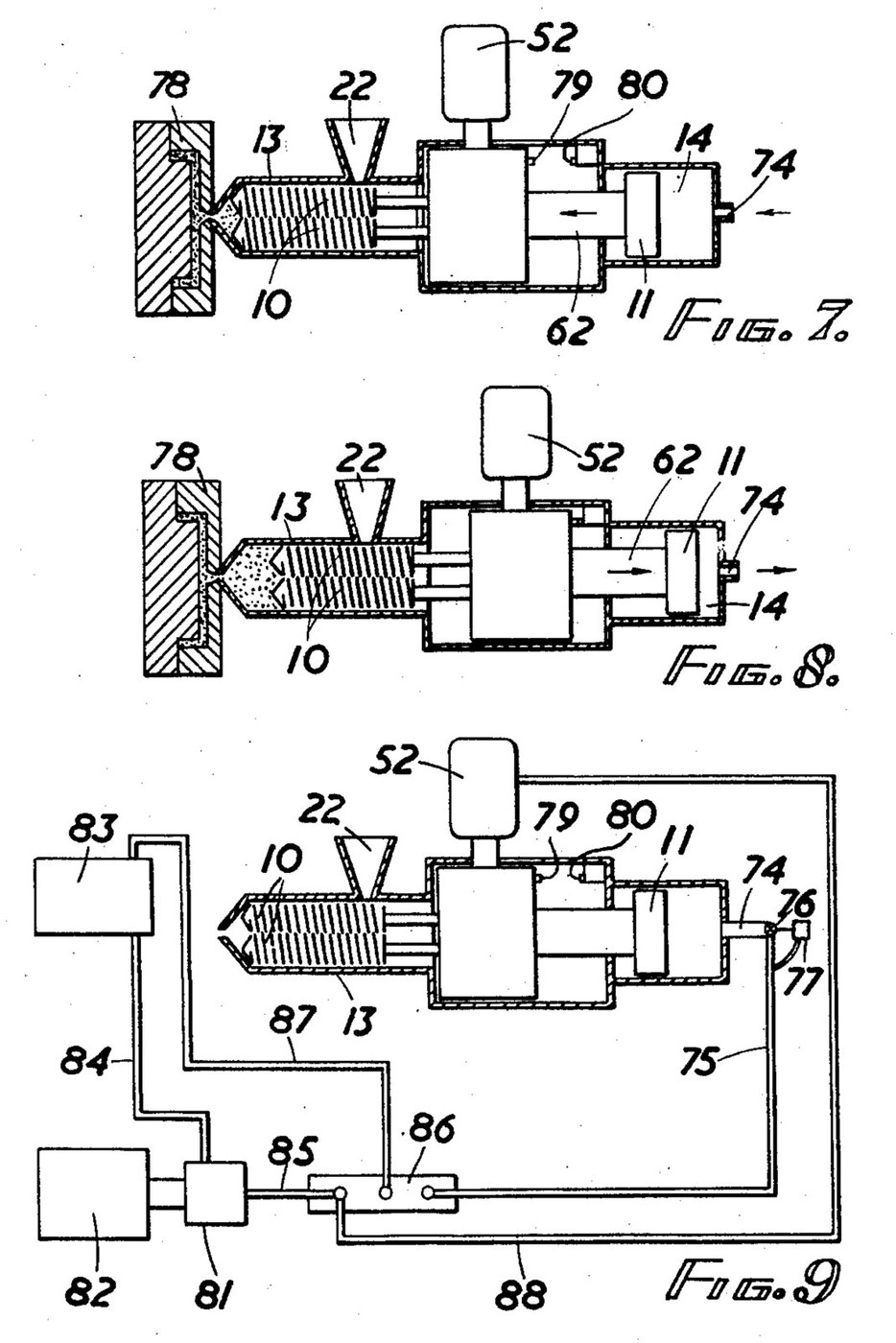


Injection Moulding Machine: Twin Intermeshing Screws as Plasticiser and Ram (Baigent, US 2,916,769)
An injection moulding machine melts plastic granules in a heated barrel and forces the melt into a mould. K. H. Baigent (US 2,916,769, 1959) does both jobs with one pair of intermeshing screws: turning, they melt, mix and pack the plastic at the nozzle; pushed forward by a hydraulic piston, they act as the ram.
Two screws are used because a single screw pushed as a ram lets too much melt flow back along its thread. At the outlet end each of his screws' threads nearly fills the gap in the other's, which seals against backflow.
Source: K. H. Baigent, "Injection Moulding Machines", US Patent 2,916,769 (filed 1957, granted 1959). Picture: its Figs. 7-9.
Avançado
Unknown
Instruções
1
1
Read Baigent
Read Baigent
"It has proven, as a practical matter, impossible to use a single screw as both an injection ram and a mixer or plasticiser, since when a single screw is translated forward to force the plastic material through the nozzle, a substantial portion thereof tends to flow backward between the threads of the screw."
2
2
Cut the twin screws
Cut the twin screws
Cut two intermeshing screws of the same outside diameter all along, so they can slide as a ram. Baigent's example: root diameter about 2.05 in., outside diameter about 3.06 in., pitch 1 in. In the outlet section the thread's outer face is about 0.30 in. deep axially with the leading face sloping 13° to the root, so each thread nearly fills the gap in the other screw. In the inlet section cut the leading face back to 31°, leaving 0.15 in., which gives about 1 1/2 times the swept volume of the outlet. Give each screw a splined end with a tapped bore. Screw length and metal are not given.
Materiais para este passo:
 Metal desconhecido2 screws
Ferramentas necessárias:
 Torno mecânico
 Fresadora
 Jogo de machos e cossinetes
 Dimensões desconhecidas
3
3
Make the barrel
Make the barrel
Bore a barrel (injection chamber) to take both screws side by side. Bolt a nozzle head on its outer end and screw in the injection nozzle. Cut a feed inlet near the other end under a hopper whose throat has a water-cooling jacket, so the granules do not melt before they enter. Wrap the barrel in closely spaced electric resistance heaters, with one more round the nozzle head. Clamp the barrel to its supports on the base. Bore, metal and heater ratings are not given.
Materiais para este passo:
Metal desconhecido1 barrel, nozzle head and nozzleMetal desconhecido1 hopper and water jacket Elemento de aquecimento2 barrel and nozzle heaters
Ferramentas necessárias:
Torno mecânico Engenho de furar
 Jogo de brocasJogo de machos e cossinetesDimensões desconhecidas
4
4
Build the sliding drive
Build the sliding drive
Build a gear box that slides on guide rails on a slide bed in line with the barrel. Run a hollow drive shaft for each screw in roller bearings, coupled to its screw by a splined sleeve and a tie rod through the shaft. Key a pinion on each shaft; both mesh inside opposite sides of one ring gear with internal teeth, so the screws turn at the same speed in the same direction. Cut worm teeth round the outside of the ring and drive it with a worm on the upright shaft of a hydraulic motor, in ball bearings.
Materiais para este passo:
Metal desconhecido1 gear box, shafts, pinions, ring and worm Rolamento de rolos4 peças
 Rolamento de esferas2 peças
Ferramentas necessárias:
Torno mecânicoFresadora Máquina de fresar engrenagens por fresa-mãe
 Chave inglesa
5
5
Fit the ram cylinder and hydraulics
Fit the ram cylinder and hydraulics
Bolt a hydraulic cylinder to the frame behind the gear box and bolt its piston rod to the gear box's thrust plate, so screws, gear box and piston slide as one. Feed the cylinder through a spring-loaded check valve, with a second, adjustable check valve on a branch that restricts the return flow: this sets the back pressure the melt must build before the screws are pushed back. An electric motor drives a hydraulic pump from a reservoir, through a solenoid-worked multiway pilot valve that sends oil either to the hydraulic motor or to the cylinder. Put a stop on the gear box and a limit switch where it ends its return stroke, and a time switch for the cooling period. Pressures are not given.
Materiais para este passo:
 Cilindro hidráulico1 peça
 Válvula de retenção2 peças
 Electroválvula1 multiway pilot valve
 Motor elétrico1 pump drive
 Tubo hidráulico1 peça
 Óleo hidráulico1 peça
Ferramentas necessárias:
Chave inglesa6
6
Run a cycle
Run a cycle
Close the nozzle with the mould, fill the hopper with granules or powder and switch on the heaters to bring the barrel up to temperature. Start the hydraulic motor: the turning screws melt the plastic and pack it at the nozzle, and are forced back against the counter pressure until the stop trips the limit switch. The pilot valve then stops the motor and drives the piston forward, so the screws ram the melt into the mould. Everything stands still while the article cools; the time switch then restarts the motor for the next shot. How the mould is clamped and opened is not given.
Materiais
10- 1 gear box, shafts, pinions, ring and wormReferência
- 2 barrel and nozzle heatersReferência
- 4 peçasReferência
- Referência
- 1 peçaReferência
- 2 peçasReferência
- Referência
- 1 pump driveReferência
- 1 peçaReferência
- 1 peçaReferência
Este projeto faz
CC0 Domínio Público
Este blueprint é liberado sob CC0. Você é livre para copiar, modificar, distribuir e usar este trabalho para qualquer finalidade, sem pedir permissão.
Apoie o Maker comprando produtos através do Blueprint, onde ele ganha uma Comissão Maker definida pelos vendedores, ou crie uma nova versão deste Blueprint e inclua-o como conexão no seu próprio Blueprint para compartilhar receita.