
ARTE
BELEZA E BEM-ESTAR
ARTESANATO
CULTURA E HISTÓRIA
ENTRETENIMENTO
MEIO AMBIENTE
COMIDA E BEBIDAS
ENGENHARIA REVERSA
CIÊNCIAS
ESPORTES
TECNOLOGIA
TECNOLOGIA VESTÍVEL
Metal Band Saw: Horizontal Saw on a Welded Steel Frame
Martin

Criado por

Martin

23. outubro 2026NO
5
0
0
0
0

Metal Band Saw: Horizontal Saw on a Welded Steel Frame

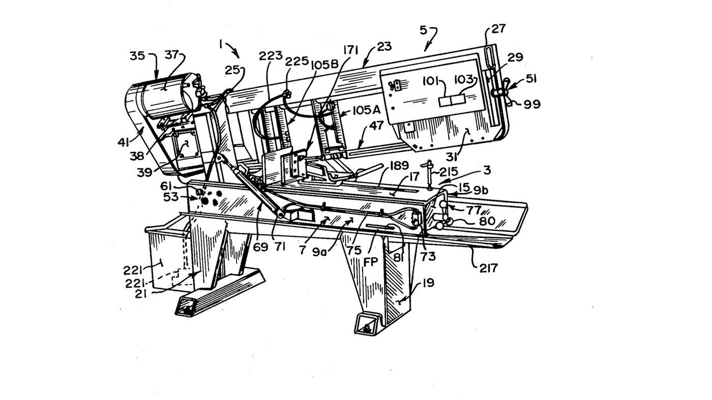
Curtis Eccardt's horizontal power band saw (Emerson Electric, US 4,364,294, 1982), built from welded steel channel and tube instead of iron castings to cut its cost. The saw head swings down on trunnions over the bed; a hydraulic cylinder with a valve sets how fast it feeds, a spring counterbalances it, and a spring tensioner shows the blade tension on a scale. Two guides with rollers twist the blade's lower run 90° so its teeth face down into the work, and carbide inserts hold it there. The patent gives no sizes, speeds or ratings; the welder and wrenches are ours. The picture: the patent's Fig. 1.
Avançado
4 days

Instruções

1

Weld the bed

Stand two steel channels (9a, 9b) parallel, webs upright and flanges facing in, and weld gussets (15) between their webs. Bolt a bed plate (17) across the top flanges as the work surface. Ours: MIG welder, drill press for the bolt holes.

Materiais para este passo:

Perfil de aço em UPerfil de aço em U2 peças
Chapa grossa de aço macioChapa grossa de aço macio1 peça
Parafuso de cabeça hexagonal - classe 8.8Parafuso de cabeça hexagonal - classe 8.81 peça

Ferramentas necessárias:

Máquina de soldar MIGMáquina de soldar MIG
Engenho de furarEngenho de furar
Chave inglesaChave inglesa
2

Weld and bolt on the legs

Weld formed sheet-steel legs onto horizontal floor members to make front and rear leg weldments (19, 21), and bolt them under the bed.

Materiais para este passo:

Chapa de açoChapa de aço1 peça
Tubo de açoTubo de aço1 peça
Parafuso de cabeça hexagonal - classe 8.8Parafuso de cabeça hexagonal - classe 8.81 peça

Ferramentas necessárias:

Máquina de soldar MIGMáquina de soldar MIG
Chave inglesaChave inglesa
3

Weld the head

Weld a head post (25) of square or rectangular steel tube square to a head beam (27) of rectangular tube. Weld a bracket leg (29) down from the beam's outer end, and fix support plates at both ends (31, 33).

Materiais para este passo:

Tubo de açoTubo de aço1 peça
Chapa grossa de aço macioChapa grossa de aço macio1 peça

Ferramentas necessárias:

Máquina de soldar MIGMáquina de soldar MIG
4

Fit the trunnions and align the pivot

Fix a shaft through the head post with its ends out as trunnions (55a, 55b), in bushings in two bearing blocks (59a, 59b) bolted inside the channel webs. Each block has one close-fit bolt hole and three oversize ones: shift the blocks until the pivot is parallel to the bed plate, then torque the bolts. A set screw (67) takes out end play.

Materiais para este passo:

Veio de açoVeio de aço1 peça
Bucha metálicaBucha metálica2 peças
Suporte de rolamentoSuporte de rolamento2 peças
Parafuso de cabeça hexagonal - classe 8.8Parafuso de cabeça hexagonal - classe 8.88 peças
Parafuso sem cabeça de ponta côncavaParafuso sem cabeça de ponta côncava1 peça

Ferramentas necessárias:

Engenho de furarEngenho de furar
Chave dinamométricaChave dinamométrica
5

Mount motor, belt drive and gearbox

Mount the electric motor (37) on a plate (38) pivoted on the head beam, and couple it by a multi-speed belt and pulleys (41) to a gearbox (39). Fit the drive wheel (43) on the gearbox output shaft.

Materiais para este passo:

Motor elétricoMotor elétrico1 peça
Chapa grossa de aço macioChapa grossa de aço macio1 peça
Correia de transmissãoCorreia de transmissão1 peça
RoldanaRoldana1 peça
Caixa redutoraCaixa redutora1 peça
Volante de serra de fitaVolante de serra de fita1 peça

Ferramentas necessárias:

Chave inglesaChave inglesa
6

Build the idler tensioner

Weld an idler yoke (87) of rolled steel plate, pivot it on the head beam with a pin (89), and cantilever the idler axle from it with the idler wheel (45) on bearings (85). A threaded rod (91) pulls the yoke through a coil spring (93) held between compression plates and a U-bolt (97); a knob (99) turns the rod. An indicator (101) on the spring reads the tension on a scale (103).

Materiais para este passo:

Chapa grossa de aço macioChapa grossa de aço macio1 peça
Pino de açoPino de aço1 peça
Veio de açoVeio de aço1 peça
Volante de serra de fitaVolante de serra de fita1 peça
Rolamento de esferasRolamento de esferas1 peça
Varão roscadoVarão roscado1 peça
Coil SpringCoil Spring1 peça
Abraçadeira em UAbraçadeira em U1 peça
Botão de comandoBotão de comando1 peça

Ferramentas necessárias:

Máquina de soldar MIGMáquina de soldar MIG
Chave inglesaChave inglesa
7

Build the two blade guides

In each guide channel (111) mount two guide rollers (115a, 115b) on ball bearings on eccentric bushings, one fixed and one adjusted to the blade thickness. Add a carbide thrust insert (133) on the blade's back edge and two carbide side inserts (137a fixed, 137b on a sprung swing bracket set by a bolt and knob). Clamp the guides on two bar tracks (107).

Materiais para este passo:

Rolo guiaRolo guia4 peças
Rolamento de esferasRolamento de esferas4 peças
Bucha excêntricaBucha excêntrica4 peças
Pastilha de carbonetoPastilha de carboneto6 peças
Coil SpringCoil Spring2 peças
Botão de comandoBotão de comando2 peças
Tubo de açoTubo de aço1 peça

Ferramentas necessárias:

Chave inglesaChave inglesa
8

Fit the blade and set the tension

By hand, run the endless blade (47) round the drive and idler wheels and through both guides; the rollers twist its lower run about 90° so the teeth face down. Turn the tension knob until the scale shows the tension you want.

Materiais para este passo:

Lâmina de serra de fitaLâmina de serra de fita1 peça
9

Fit the feed cylinder and counterbalance

Connect a hydraulic cylinder (71) between bed channel and head post above the trunnions, filled with oil and piped through tubing (75) to a control valve (73): the valve sets the feed rate and, closed, holds the head. Fit a coil spring (78) on a threaded linkage (79) between an end gusset and the head post below the trunnions, adjusted by a knob (80), to counterbalance the head.

Materiais para este passo:

Cilindro hidráulicoCilindro hidráulico1 peça
Óleo hidráulicoÓleo hidráulico1 batch
Tubo hidráulicoTubo hidráulico1 peça
Válvula reguladora de caudalVálvula reguladora de caudal1 peça
Coil SpringCoil Spring1 peça
Varão roscadoVarão roscado1 peça
Botão de comandoBotão de comando1 peça

Ferramentas necessárias:

Chave inglesaChave inglesa
10

Bolt on the vice

Bolt the quick-acting vice to the bed plate to clamp the work square under the blade.

Materiais para este passo:

Morsa de máquinaMorsa de máquina1 peça
Parafuso de cabeça hexagonal - classe 8.8Parafuso de cabeça hexagonal - classe 8.81 peça

Ferramentas necessárias:

Chave inglesaChave inglesa

Materiais

29

Ferramentas necessárias

4

CC0 Domínio Público

Este blueprint é liberado sob CC0. Você é livre para copiar, modificar, distribuir e usar este trabalho para qualquer finalidade, sem pedir permissão.

Apoie o Maker comprando produtos através do Blueprint, onde ele ganha uma Comissão Maker definida pelos vendedores, ou crie uma nova versão deste Blueprint e inclua-o como conexão no seu próprio Blueprint para compartilhar receita.

Discussão

(0)

Entrar para participar da discussão

Carregando comentários...