ARTE
BELEZA E BEM-ESTAR
ARTESANATO
CULTURA E HISTÓRIA
ENTRETENIMENTO
MEIO AMBIENTE
COMIDA E BEBIDAS
ENGENHARIA REVERSA
CIÊNCIAS
ESPORTES
TECNOLOGIA
TECNOLOGIA VESTÍVEL
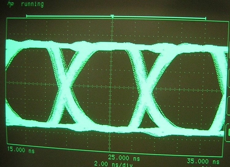


FM and MFM: Making the Data Clock Itself
A read head is a differentiator. It produces a voltage proportional to the RATE OF CHANGE of flux, which means a stretch of uniform magnetisation produces exactly nothing no matter how long it is. Record a thousand zeros and the head is silent; record a million and it is equally silent. The drive cannot tell them apart.
It could count them with a clock, but it has no clock worth trusting. The spindle wanders by a percent or two with temperature and supply voltage, the disc was probably written in a different drive on a different day, and a percent of error accumulated over a few hundred bits puts everything in the wrong place.
So the clock is built into the data. Frequency Modulation recording puts a transition at every cell boundary as a clock, plus one in the middle of the cell for a 1 — self-clocking, completely reliable, and it spends half of every transition on saying nothing. Modified FM noticed that the clock transition is only NEEDED between two consecutive zeros, dropped it everywhere else, and doubled the density of every floppy disk in the world without touching the head or the medium. That is what the labels single density and double density meant.
FULLY BUILDABLE, and the exercise is the point: encode, decode, then walk the clock error up until the decoder fails. The error at which it breaks IS the detection window, and that number governs everything about how dense a drive can be.
Intermediário
4 hours
Instruções
1
1
Do it once by hand
Do it once by hand
Take the byte 10100011 and write out its FM cell stream on paper: for each data bit, a clock cell that is always 1, then a data cell equal to the bit. Sixteen cells.
Now MFM the same byte. Same layout, but the clock cell is 1 only when the PREVIOUS data bit and this one are both 0. Count the 1s in each stream — those are flux reversals, and they are what actually gets written.
Then draw both as waveforms, flipping the line up or down at every 1. Two pictures of the same byte. The MFM one has fewer corners in it, and that difference is a doubling of the capacity of every floppy disk ever sold.
2
2
Encode, decode, and break it
Encode, decode, and break it
Flash the sketch and open the serial monitor at 115200. It encodes five bytes to MFM, turns the cell stream into transition TIMES, applies a deliberate clock error, and recovers the data with a software phase-locked loop.
It then walks the error from 0 to 30 percent and prints where the decode fails. Watch what happens around the failure point: it does not degrade gently, it goes from perfect to garbage within a percent or two. A run of zeros is where it breaks first, which is exactly why the maximum run length matters.
Put an LED and a 330 ohm resistor on GPIO19 so each recovered transition blinks, and a second on GPIO18 for the raw flux waveform. At a slow data rate you can watch the code working before you ever reach for the scope.
Change the message to all 0x00 and re-run. MFM's clock cells save it. Then disable the clock cells in `encodeMFM` and re-run: it fails immediately, at zero error.
mfm_codec.inocpp
Materiais para este passo:
 Sortido de LED1 peça
 Kit de resistências1 peça
Ferramentas necessárias:
 Placa de desenvolvimento ESP32
 Computador de secretária
 Osciloscópio digital
 Conjunto de fios de ligação
 Breadboard - Classic
3
3
Density ratio, and the drift budget
Density ratio, and the drift budget
A carregar o notebook Jupyter…
Ferramentas necessárias:
Computador de secretária4
4
Compendium: three constraints, one code
Compendium: three constraints, one code
DC BALANCE, WHICH MFM IGNORES. A read channel is AC-coupled, because the head makes no DC. A code that allows long stretches at one polarity makes the baseline wander and the detector's threshold with it. EFM on the compact disc spends three merging bits per symbol almost entirely on this; MFM does not bother, and floppy drives paid for it with finicky read amplifiers.
THE SIBLING, ANNOUNCED. RLL(2,7) is blueprint 7: same rate 1/2, minimum run raised from 1 to 2, density ratio 1.0 to 1.5. The whole difference is what the decoder must remember.
AGAINST PARITY. The parity blueprint adds redundancy to DETECT an error. A channel code adds redundancy so the signal can be READ at all. Different jobs, and they stack — real drives do both.
Materiais
2- 1 peçaReferência
- desdeR$29.33
Ferramentas necessárias
5- Referência
- Referência
- Osciloscópio digital10% de comissãoMagento Legacy Storeships internationallyReferência
- Referência
- Breadboard - Classic10% de comissãoR$49.03
Blueprints relacionados
Estes blueprints compartilham conhecimento — técnicas, materiais ou princípios

CC0 Domínio Público
Este blueprint é liberado sob CC0. Você é livre para copiar, modificar, distribuir e usar este trabalho para qualquer finalidade, sem pedir permissão.
Apoie o Maker comprando produtos através do Blueprint, onde ele ganha uma Comissão Maker definida pelos vendedores, ou crie uma nova versão deste Blueprint e inclua-o como conexão no seu próprio Blueprint para compartilhar receita.