ARTE
BELEZA E BEM-ESTAR
ARTESANATO
CULTURA E HISTÓRIA
ENTRETENIMENTO
MEIO AMBIENTE
COMIDA E BEBIDAS
ENGENHARIA REVERSA
CIÊNCIAS
ESPORTES
TECNOLOGIA
TECNOLOGIA VESTÍVEL
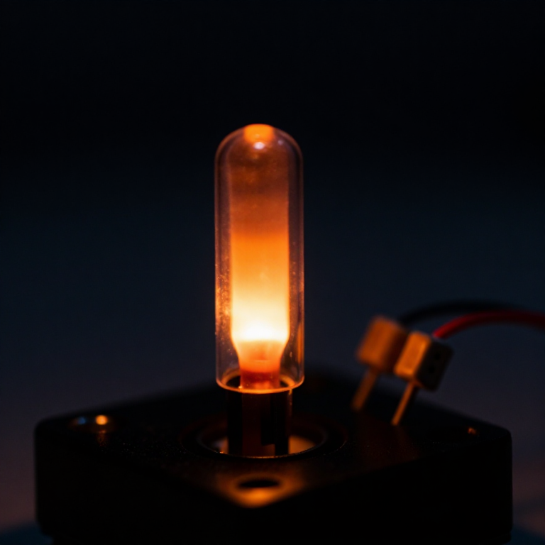


The Negative Feedback Amplifier
A telephone line across a continent needs hundreds of amplifiers in series, and their faults add. Each valve's gain drifts as it ages and each stage adds a little distortion, so a hundred repeaters each drifting one decibel is a hundred decibels of drift. Bell Labs spent the 1920s hand-selecting valves, matching them in pairs and re-matching them every year, and it was not working.
Harold Black tried the obvious fix first. His 1923 feedforward amplifier separated out the distortion, amplified it on its own, and subtracted it from the output further down. It works on the bench and it needs two active paths matched to about one per cent and HELD there while the valves age and the room warms up. Nothing in 1923 could do that.
On the morning of 2 August 1927, crossing the Hudson on the Lackawanna Ferry, he wrote the other answer on a spare copy of the New York Times. Feed a fraction of the output back to the input in opposition, and the closed-loop gain becomes A over one plus A-beta. Make the loop gain large and that collapses to one over beta - a number set by two resistors, which do not age, do not distort and cost nothing to match.
One decision buys four things at once, all divided or multiplied by the same factor: the distortion falls, the gain drift falls, the bandwidth rises, and the amplifier's own characteristics stop mattering. The price is stated just as plainly. To keep forty decibels of gain with forty decibels of feedback you must build eighty and throw half of it away.
It also buys a problem nobody had before. A loop can howl, and in 1927 there was no way to predict which one would.
Intermediário
3 hours
Instruções
1
1
An amplifier with no feedback at all
An amplifier with no feedback at all
Build a common-emitter stage on the breadboard: 2N3904, 4k7 collector load, base biased near half the supply, emitter straight to ground through a 220 uF capacitor.
Feed it 10 mV at 1 kHz and measure the output. Note the gain. Then warm the transistor with your finger and watch the gain move.
Materiais para este passo:
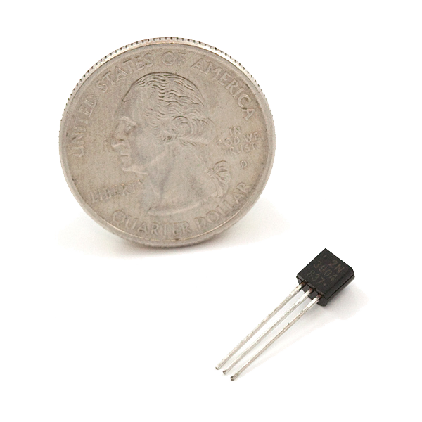 BJT Transistors - NPN 2N39041 peça
 1/4W Resistor Kit (600pcs, 30 Values)1 kit
 Electrolytic Capacitor Kit (200pcs, 15 Values)1 kit
Ferramentas necessárias:
 Breadboard - Classic
 DDS Signal Generator (1Hz-65MHz)
 Digital Oscilloscope
 Bench Power Supply (30V/5A)
 Digital Multimeter (Lab Grade)
2
2
Take the capacitor out
Take the capacitor out
Remove the emitter bypass capacitor so the emitter resistor is in circuit for signal. You have just closed a feedback loop: the emitter voltage follows the output current and opposes the input.
Re-measure. The gain has collapsed to roughly the ratio of two resistors - and now it does not move when you warm the transistor, and the sine wave on the scope is visibly cleaner at large signals. Same parts, one component moved.
Materiais para este passo:
1/4W Resistor Kit (600pcs, 30 Values)1 kitFerramentas necessárias:
Breadboard - ClassicDDS Signal Generator (1Hz-65MHz)Digital OscilloscopeDigital Multimeter (Lab Grade)3
3
One over beta, four benefits, and the thing Black tried first
One over beta, four benefits, and the thing Black tried first
A carregar o notebook Jupyter…
Ferramentas necessárias:
 Desktop Computer
4
4
Compendium: the patent nobody believed, and the minus sign
Compendium: the patent nobody believed, and the minus sign
The British Patent Office initially treated the application the way they treated perpetual motion machines, on the reasonable-sounding grounds that an amplifier whose output opposes its input cannot amplify. It is a fair objection and the answer is that it does not amplify - the LOOP does, and what the loop delivers is not gain but accuracy. Black's US patent 2,102,671 was filed in 1932 and granted in 1937, ten years after the ferry. Bell System repeaters using it went into service in the 1930s and the same equation now sits under every operational amplifier, every switching regulator and every servo in this batch.
The minus sign is worth being careful about, because it is only a minus sign at low frequency. Every real amplifier adds phase shift as frequency rises, and at some frequency the feedback that was subtracting arrives 180 degrees late and starts adding instead. If the loop gain is still above one when that happens, the amplifier oscillates. More feedback makes every static property better and moves that frequency closer, which is why the Bell amplifiers with the most feedback were the ones that sang - and why the next two blueprints exist.
Materiais
3- BJT Transistors - NPN 2N390410% de comissão1 peçaR$3.93
- 1 kitReferência
- Referência
Ferramentas necessárias
6- Breadboard - Classic10% de comissãoR$48.79
- Referência
- Digital Oscilloscope10% de comissãoMagento Legacy Storeships internationallyReferência
- Referência
- Referência
- Referência
Total estimado
O que quem fez comprou. Os materiais sem preço obtêm-se onde os comprares.
Blueprints relacionados
Estes blueprints compartilham conhecimento — técnicas, materiais ou princípios

CC0 Domínio Público
Este blueprint é liberado sob CC0. Você é livre para copiar, modificar, distribuir e usar este trabalho para qualquer finalidade, sem pedir permissão.
Apoie o Maker comprando produtos através do Blueprint, onde ele ganha uma Comissão Maker definida pelos vendedores, ou crie uma nova versão deste Blueprint e inclua-o como conexão no seu próprio Blueprint para compartilhar receita.