// Pocket Morse code decoder - ATmega328P-AU, internal 8 MHz, CR2032
// Board: Arduino Pro or Pro Mini, ATmega328P (3.3V, 8MHz) - burn fuses for internal RC (see notes)
// 27 LEDs charlieplexed on A0..A5 (PC0..PC5), button on D2 (INT0) to GND.
#include <avr/sleep.h>
#include <avr/power.h>
#include <avr/interrupt.h>

// ---------------- timing constants (ms) ----------------
const unsigned long DEBOUNCE_MS       = 20;     // button debounce
const unsigned long DASH_THRESHOLD_MS = 250;    // press shorter = dot, longer = dash
const unsigned long CHAR_GAP_MS       = 700;    // silence that ends a character
const unsigned long BLINK_ON_MS       = 150;    // result blink on time
const unsigned long BLINK_OFF_MS      = 150;    // result blink off time
const uint8_t       BLINK_COUNT       = 3;      // number of result blinks
const unsigned long IDLE_SLEEP_MS     = 30000;  // idle time before power-down

// ---------------- hardware ----------------
const uint8_t BUTTON_PIN = 2;                   // INT0, internal pull-up, active low
const uint8_t LINE_PINS[6] = {A0, A1, A2, A3, A4, A5};  // charlieplex lines CP1..CP6
const uint8_t MAX_CODE_LEN = 4;

struct Node {
  const char *code;   // "" = Start
  char label;
  uint8_t anode;      // index into LINE_PINS
  uint8_t cathode;
};

const Node NODES[] = {
  {"", ' ', 0, 2},   // D1
  {"-", 'T', 2, 0},   // D2
  {".", 'E', 1, 0},   // D3
  {"--", 'M', 2, 1},   // D4
  {"-.", 'N', 5, 1},   // D5
  {".-", 'A', 4, 1},   // D6
  {"..", 'I', 0, 1},   // D7
  {"---", 'O', 1, 2},   // D8
  {"--.", 'G', 2, 4},   // D9
  {"-.-", 'K', 1, 5},   // D10
  {"-..", 'D', 5, 3},   // D11
  {".--", 'W', 1, 4},   // D12
  {".-.", 'R', 3, 1},   // D13
  {"..-", 'U', 0, 4},   // D14
  {"...", 'S', 5, 0},   // D15
  {"--.-", 'Q', 5, 2},   // D16
  {"--..", 'Z', 4, 2},   // D17
  {"-.--", 'Y', 2, 5},   // D18
  {"-.-.", 'C', 5, 4},   // D19
  {"-..-", 'X', 4, 5},   // D20
  {"-...", 'B', 3, 5},   // D21
  {".---", 'J', 4, 3},   // D22
  {".--.", 'P', 3, 4},   // D23
  {".-..", 'L', 1, 3},   // D24
  {"..-.", 'F', 4, 0},   // D25
  {"...-", 'V', 0, 3},   // D26
  {"....", 'H', 3, 0},   // D27
};
const uint8_t NODE_COUNT = sizeof(NODES) / sizeof(NODES[0]);
const int8_t START_NODE = 0;

// ---------------- state ----------------
char seq[MAX_CODE_LEN + 2];
uint8_t seqLen = 0;
bool seqInvalid = false;
bool charPending = false;
bool btnStable = false;          // true = pressed
bool btnLastRaw = false;
unsigned long btnRawChange = 0;
unsigned long pressStart = 0;
unsigned long lastRelease = 0;
unsigned long lastActivity = 0;

void ledsOff() {
  for (uint8_t i = 0; i < 6; i++) {
    pinMode(LINE_PINS[i], INPUT);
    digitalWrite(LINE_PINS[i], LOW);
  }
}

void ledOn(int8_t idx) {
  ledsOff();
  if (idx < 0 || idx >= NODE_COUNT) return;
  uint8_t a = LINE_PINS[NODES[idx].anode];
  uint8_t c = LINE_PINS[NODES[idx].cathode];
  digitalWrite(c, LOW);
  pinMode(c, OUTPUT);
  digitalWrite(a, HIGH);
  pinMode(a, OUTPUT);
}

int8_t findNode(const char *code) {
  for (uint8_t i = 0; i < NODE_COUNT; i++) {
    if (strcmp(NODES[i].code, code) == 0) return i;
  }
  return -1;
}

void blinkNode(int8_t idx) {
  for (uint8_t k = 0; k < BLINK_COUNT; k++) {
    ledsOff();
    delay(BLINK_OFF_MS);
    ledOn(idx);
    delay(BLINK_ON_MS);
  }
  ledsOff();
  delay(BLINK_OFF_MS);
}

bool rawPressed() { return digitalRead(BUTTON_PIN) == LOW; }

// returns +1 on debounced press, -1 on debounced release, 0 otherwise
int8_t pollButton(unsigned long now) {
  bool raw = rawPressed();
  if (raw != btnLastRaw) { btnLastRaw = raw; btnRawChange = now; }
  if (raw != btnStable && (now - btnRawChange) >= DEBOUNCE_MS) {
    btnStable = raw;
    return raw ? 1 : -1;
  }
  return 0;
}

void resetSequence() {
  seqLen = 0;
  seq[0] = 0;
  seqInvalid = false;
  charPending = false;
}

ISR(INT0_vect) {
  EIMSK &= ~_BV(INT0);   // one-shot wake interrupt
}

void waitForRelease() {
  unsigned long t = millis();
  while (true) {
    if (rawPressed()) t = millis();
    if (millis() - t >= DEBOUNCE_MS) break;
  }
  btnStable = false; btnLastRaw = false;
}

void goToSleep() {
  ledsOff();
  set_sleep_mode(SLEEP_MODE_PWR_DOWN);
  cli();
  EICRA &= ~(_BV(ISC01) | _BV(ISC00));   // INT0 on low level (works in power-down)
  EIFR = _BV(INTF0);
  EIMSK |= _BV(INT0);
  sleep_enable();
  sleep_bod_disable();
  sei();
  sleep_cpu();
  sleep_disable();
  EIMSK &= ~_BV(INT0);
  // woken by the button: this press only wakes the board
  waitForRelease();
}

void wakeUp() {
  resetSequence();
  ledOn(START_NODE);
  lastActivity = millis();
}

void setup() {
  ADCSRA = 0;
  power_adc_disable();
  power_spi_disable();
  power_twi_disable();
  power_usart0_disable();
  power_timer1_disable();
  power_timer2_disable();
  ACSR = _BV(ACD);                 // analog comparator off
  DIDR0 = 0x3F;                    // digital input buffers off on PC0..PC5 (outputs only)
  for (uint8_t p = 0; p <= 13; p++) pinMode(p, INPUT_PULLUP);  // unused pins defined
  pinMode(BUTTON_PIN, INPUT_PULLUP);
  ledsOff();
  delay(5);
  btnLastRaw = btnStable = rawPressed();
  wakeUp();
}

void loop() {
  unsigned long now = millis();
  int8_t ev = pollButton(now);

  if (ev == 1) {                         // press
    pressStart = now;
    lastActivity = now;
  } else if (ev == -1) {                 // release: classify
    unsigned long dur = now - pressStart;
    char sym = (dur < DASH_THRESHOLD_MS) ? '.' : '-';
    if (seqLen < MAX_CODE_LEN) {
      seq[seqLen++] = sym;
      seq[seqLen] = 0;
    } else {
      seqInvalid = true;
    }
    int8_t idx = seqInvalid ? -1 : findNode(seq);
    if (idx < 0) { seqInvalid = true; ledsOff(); }
    else ledOn(idx);
    charPending = true;
    lastRelease = now;
    lastActivity = now;
  }

  if (charPending && !btnStable && (now - lastRelease) >= CHAR_GAP_MS) {
    int8_t idx = seqInvalid ? -1 : findNode(seq);
    if (idx >= 0) blinkNode(idx);
    else blinkNode(START_NODE);
    resetSequence();
    ledOn(START_NODE);
    lastActivity = millis();
  }

  if (!charPending && !btnStable && (millis() - lastActivity) >= IDLE_SLEEP_MS) {
    goToSleep();
    wakeUp();
  }
}
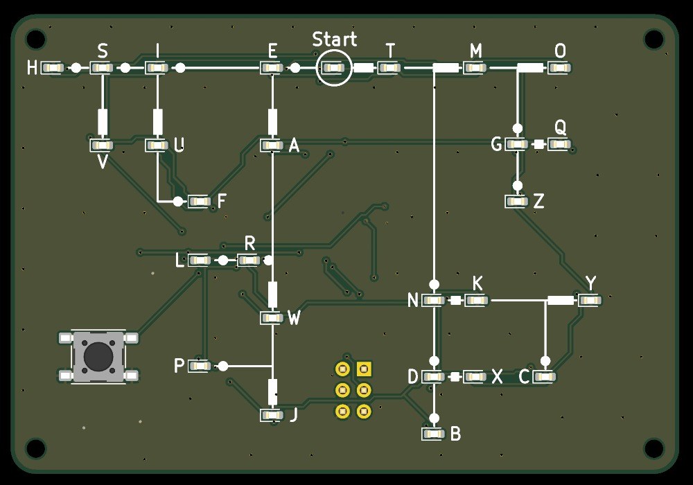

 Placa de circuito impresso1 peça
 Computador com o IDE Arduino
 Microcontrolador ATmega328P1 peça
 LED de chip27 peças
 Resistor de chip7 peças
 Condensador cerâmico de chip3 peças
 Botão de pressão1 peça
 Suporte de pilhas1 peça
 Pasta de solda (sem chumbo)1 peça
 Fio de solda1 peça
 Estação de retrabalho de ar quente
 Ferro de soldar
 Pinça de pontas finas
 Fluxo
 Lupa
 Multímetro
 Álcool isopropílico a 99 %
 Programador AVR ISP
 Filamento de PLA1 peça
 Parafuso autoatarraxante4 peças
 Pilha de botão CR20321 peça
 Impressora 3D de filamento (FDM)
 Paquímetro
 Conjunto de chaves de fendas de precisão