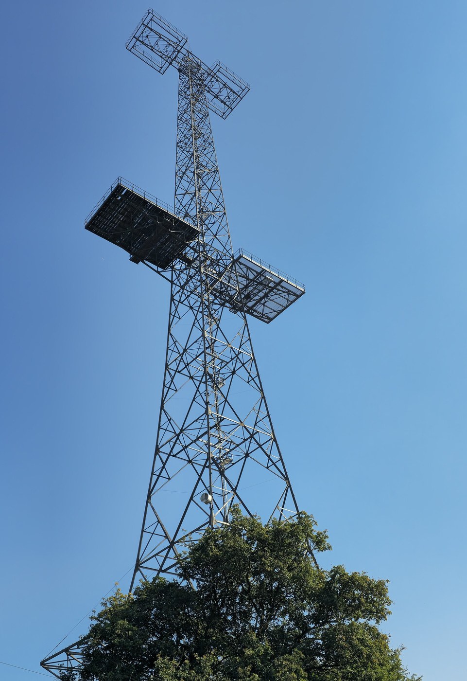


Pulse Radar and the Chain Home
Instruções
Measure the speed of light with an echo
Measure the speed of light with an echo
Prove the ranging principle at a scale you can lay a tape measure along.
- Build a pulse generator producing short pulses — under 100 ns — at a low repetition rate.
- Feed the pulses into a long length of coaxial cable with the far end left OPEN.
- Watch the sending end on a fast oscilloscope.
- Measure the delay between the outgoing pulse and the reflection, and divide twice the cable length by that time.
You will measure roughly two-thirds the speed of light, because signals travel slower in a dielectric than in vacuum — that ratio is the cable’s velocity factor. Now short the far end instead: the reflection returns INVERTED. An open end reflects in phase, a short reflects out of phase, and a correctly matched load produces no reflection at all.
That is radar in miniature. It is also exactly how cable faults are located today, with a time-domain reflectometer — and the polarity of the reflection tells you whether the fault is a break or a short.
Note the resolution limit already: two reflections closer together than one pulse length merge into one. Range resolution is set by pulse LENGTH, not by anything else, and that trade dominates the rest of this blueprint.Materiais para este passo:
 Cabo coaxial (RG-58)1 reel
 Kit de resistências1 kit
 Kit de condensadores1 kit
 Placa perfurada / placa de prototipagem1 peça
 Fio de solda 63/37 com alma de resina1 reel
Ferramentas necessárias:
 Osciloscópio
 Gerador de funções
 Paquímetro digital de 6 polegadas
 Fita métrica
 Multímetro digital de laboratório
 Estação de soldagem
 Óculos de segurança transparentes
Work out the fourth-power problem
Work out the fourth-power problem
Understand why radar needs so much power and such sensitive receivers.
- Consider a pulse leaving the antenna and spreading over a sphere — its power density falls as the square of range.
- The target intercepts a small part of that and re-radiates it, again spreading over a sphere on the return.
- Multiply the two effects.
- Compute how much weaker an echo is at 200 km than at 100 km.
Received echo power falls as the FOURTH power of range: doubling the distance costs a factor of sixteen. To double your detection range you need sixteen times the transmitter power, or sixteen times the antenna gain, or some combination — which is why radar transmitters are measured in megawatts and radar antennas are enormous.
It also explains a design decision that looks backwards: radar pulses are extremely short but extremely powerful, because average power is limited by what the equipment can dissipate, while detection depends on peak power in the instant of the echo. Concentrating the energy into a brief pulse buys range for free.
The other half of the answer is the receiver, and this is where the superheterodyne earns its place — a radar receiver is a superhet, and its sensitivity is set by its noise figure and its bandwidth. Everything in the first half of this batch is load-bearing here.Materiais para este passo:
 Papel milimétrico1 pad
Ferramentas necessárias:
Paquímetro digital de 6 polegadasMultímetro digital de laboratórioOsciloscópioBuild the transmit-receive switch, the hardest small problem
Build the transmit-receive switch, the hardest small problem
One antenna must both transmit megawatts and receive picowatts, microseconds apart.
- Reason about what happens if the sensitive receiver is connected while the transmitter fires.
- Study the duplexer principle: a gas-filled spark gap that conducts when a large signal is present and is transparent when it is not.
- Build a low-power analogue with back-to-back diodes protecting a sensitive input, and measure the leakage during a strong pulse.
The TR cell is a switch operated by the signal itself: the transmit pulse ionises the gas, which shorts the receiver path and protects it; when the pulse ends the gas de-ionises in microseconds and the receiver is connected again. No timing circuit, no control signal, no relay fast enough to be needed.
Recognise the pattern — this is the same family as the self-opening leading-edge slat and the over-centre landing gear lock from the aviation batch. The mechanism draws its actuation from the problem it is protecting against, so there is nothing separate to fail or to synchronise.
The recovery time sets the MINIMUM range: while the TR cell is still de-ionising, the receiver is deaf, so anything close enough to echo during that window is invisible. Every radar has a blind zone around itself, and its size is set by this one component.Materiais para este passo:
 Díodo de germânio (1N34A)4 peças
 Lâmpada indicadora de néon2 peçasKit de resistências1 kitKit de condensadores1 kit
Ferramentas necessárias:
OsciloscópioGerador de funções Gerador de sinaisMultímetro digital de laboratórioEstação de soldagemÓculos de segurança transparentes
Display range on a timebase, and find the target
Display range on a timebase, and find the target
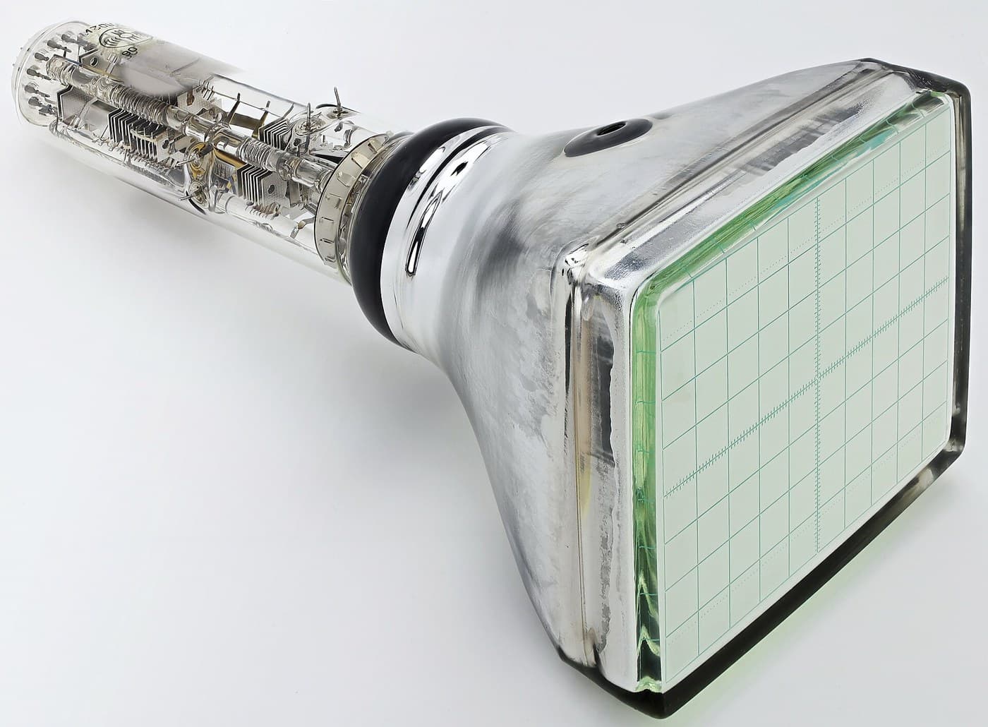
Use the cathode-ray tube from earlier in this batch to turn delay into distance.
- Trigger the oscilloscope timebase from the transmit pulse, so the sweep starts as each pulse leaves.
- Feed the receiver output to the vertical input.
- Calibrate the horizontal axis directly in kilometres using the speed of light.
- Introduce a reflecting object and read its range off the screen.
The horizontal axis is now distance, and every echo appears as a blip at its own range. This is the A-scope, the original radar display, and it shows range along one axis and nothing else.
The plan-position indicator came later and is a genuinely clever variation: rotate the timebase in step with the antenna, so the sweep is a radius that turns like a clock hand, and add a long-persistence phosphor so echoes linger after the beam has passed. The familiar circular radar picture is an A-scope drawn in polar coordinates by a rotating deflection.
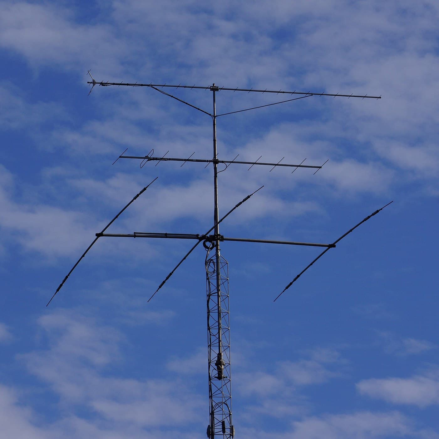
Chain Home did not scan at all. Its transmitters floodlit a whole sector from fixed masts, and direction was found by comparing signal strength on crossed receiving antennas — goniometry rather than a beam. It was cruder and it was buildable in 1937, which is the entire point.Materiais para este passo:
Kit de resistências1 kitKit de condensadores1 kitPapel milimétrico1 padFerramentas necessárias:
OsciloscópioGerador de funçõesGerador de sinaisMultímetro digital de laboratórioFita métricaÓculos de segurança transparentesTrade pulse length against range, and see the whole compromise
Trade pulse length against range, and see the whole compromise
Every radar parameter fights another one. Measure the fight.
- Vary the pulse LENGTH and measure how close two reflections can be before they merge.
- Vary the pulse REPETITION frequency and work out the maximum unambiguous range — the distance light travels in the gap between pulses, halved.
- Tabulate resolution and maximum range against both parameters.
Short pulses give fine range resolution and less energy per pulse, hence shorter detection range. A high repetition rate gives more echoes per second and a shorter unambiguous range, because an echo arriving after the next pulse has left is reported at the wrong distance entirely. That last effect produces ghost targets at false ranges and is the reason radars stagger their repetition rate — a real target holds still, a ghost jumps.
So the design is a knot: power against resolution, resolution against range, range against repetition rate, all constrained by what the transmitter can dissipate. There is no setting that is best; there is only a setting matched to a job. An air-search radar and a weather radar are the same physics tuned to opposite ends of these curves.
Pulse compression eventually cut the knot by transmitting a long pulse with a frequency sweep inside it and correlating the echo — long pulse energy with short pulse resolution. That is a genuinely different move: instead of choosing a point on the trade, it changes what is being traded.Materiais para este passo:
Cabo coaxial (RG-58)1 reelPapel milimétrico1 padFerramentas necessárias:
OsciloscópioGerador de funções Analisador de espetro / software FFTGerador de sinaisFita métricaPaquímetro digital de 6 polegadasÓculos de segurança transparentes
Materiais
8- 1 reelReferência
- desdeR$29.19
- 1 kitReferência
- Referência
- Referência
- 1 padReferência
- 4 peçasReferência
- 2 peçasReferência
Ferramentas necessárias
9- Referência
- Referência
- Referência
- 1 vendor sell this, none ship to you yetReferência
- Referência
- Referência
- Referência
- Referência
- Referência
Blueprints relacionados
Estes blueprints compartilham conhecimento — técnicas, materiais ou princípios

CC0 Domínio Público
Este blueprint é liberado sob CC0. Você é livre para copiar, modificar, distribuir e usar este trabalho para qualquer finalidade, sem pedir permissão.
Apoie o Maker comprando produtos através do Blueprint, onde ele ganha uma Comissão Maker definida pelos vendedores, ou crie uma nova versão deste Blueprint e inclua-o como conexão no seu próprio Blueprint para compartilhar receita.