Push Buttons — SIK Circuit 5
Instruções
Parts & Introduction
Parts & Introduction
Push buttons are the simplest digital input. This experiment uses two buttons with an XOR logic gate: the LED turns on if you press either button, but turns off if you press both. You'll learn about digitalRead(), pull-up resistors, and boolean logic.
Parts Needed
- 1x Arduino Uno + USB cable
- 1x Breadboard
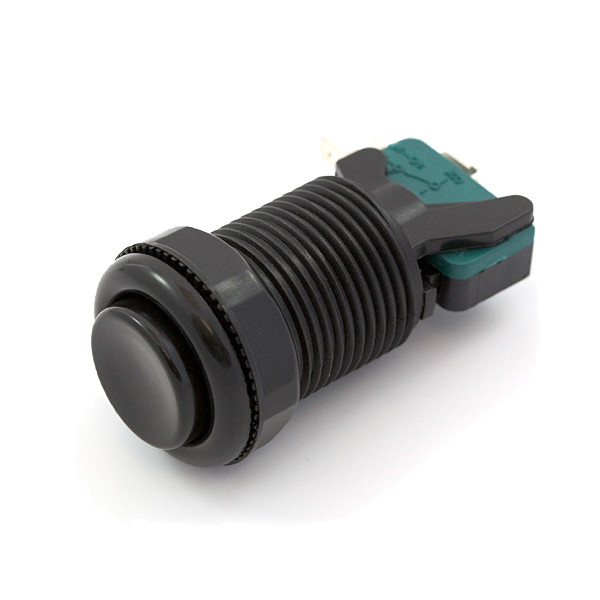
- 2x Push Buttons
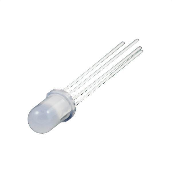
- 1x LED (any color)
- 1x 330Ω Resistor
- 2x 10KΩ Resistors (pull-ups)
- 7x Jumper Wires
Materiais para este passo:
 SparkFun Inventors Kit - V3.21 kit
 Arduino Uno R31 peça
 Breadboard1 peça
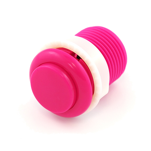 Push Button2 peças
 5mm LED1 peça
 330 Ohm Resistor1 peça10K Ohm Resistor2 peças
 Jumper Wires7 peças
Ferramentas necessárias:
Hardware Hookup
Hardware Hookup
Wiring Instructions
- Place both push buttons across the center canyon of the breadboard.
- Button 1: Connect one pin to GND. Connect the opposite diagonal pin to Arduino Digital Pin 2. Add a 10K resistor between Pin 2 and 5V (pull-up).
- Button 2: Connect one pin to GND. Connect the opposite diagonal pin to Arduino Digital Pin 3. Add a 10K resistor between Pin 3 and 5V (pull-up).
- Connect LED positive leg to Digital Pin 13, negative leg through 330Ω resistor to GND.
Note: The pull-up resistors hold the input HIGH when the button is not pressed. Pressing the button connects the pin to GND (LOW).
Materiais para este passo:
Push Button2 peças5mm LED1 peça330 Ohm Resistor1 peça10K Ohm Resistor2 peçasBreadboard1 peçaJumper Wires7 peçasArduino Code
Arduino Code
Open the Arduino IDE and upload the following sketch to your Arduino board.
Materiais para este passo:
Arduino Uno R31 peçaFerramentas necessárias:
Test & Experiment
Test & Experiment
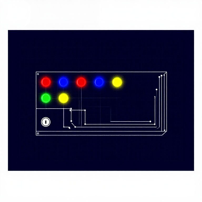
What You Should See
The LED turns on when you press either button individually. It turns off when you press both buttons simultaneously (XOR logic).
Troubleshooting
- Not responding: Push buttons are square — it's easy to put them in the wrong orientation. Try rotating 90°.
- LED always on or always off: Check the pull-up resistor connections. Without them, the input pin floats and reads random values.
Experiments to Try
- Change the logic to AND (both buttons required) or simple OR.
- Use the buttons to control an RGB LED — one button for color, one for brightness.
- Try using
INPUT_PULLUPmode to eliminate the external resistors.
Materiais
8- R$545.00
- 1 peçaReferência
- 1 peçaReferência
- 2 peçasR$7.00
- Referência
- R$14.00
- R$14.00
- R$22.00
Required Equipment
Equipment this kind of build typically needs — buy from any maker below.
- CriticalSoldering Iron·
 Helping Hands Soldering Stand
 Solder Tip Tinner and Cleaner
 SparkFun Solder-able Breadboard - Mini
 Soldering Iron
 Solder Wire
 Soldering Flux Paste (50g, Rosin-Based)
 - RecommendedBreadboard·
 JST to Breadboard Jumper (3-pin)
 Breadboard - Translucent Self-Adhesive (Clear)Solderless Breadboard 830 Points (3-Pack)SparkFun Solder-able Breadboard - Mini
 Breadboard Power Supply USB - 5V/3.3VBreadboard
 - RecommendedDust Mask / Respirator·
 Full-Face Gas Mask (ABEK multi-gas cartridge)
 Dust Mask
 Venetian Mask Blank (Papier-Mache)
 Full-Face Respirator
 Respirator Fit Test Kit
 Respirator with Acid Gas Cartridge
 - RecommendedMultimeter·
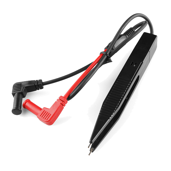 Multimeter Tweezer Probes
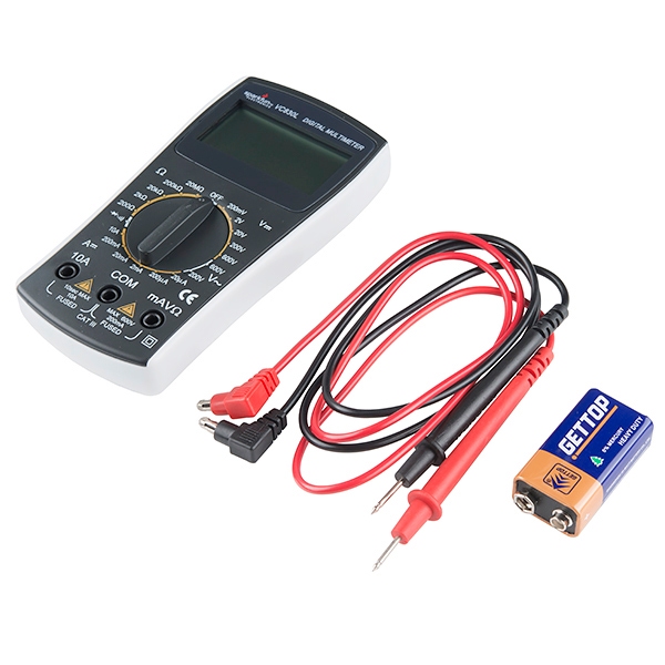 Digital Multimeter - Basic
 Digital Multimeter Pro
 Multimeter
 Digital Multimeter (Auto-Range, True RMS)Digital Multimeter
 - RecommendedSafety Glasses·
 Safety Sign (Caution/Warning)
 Splash-Proof Safety Goggles
 Reflective Safety Vest Kit (DIY)
 Chemical Splash Goggles
 Safety Netting for Rockfall
 Steel-Toed Safety Boots
 - RecommendedWire Strippers·
 Wire Strippers
 Wire Stripper & Crimping Tool (AWG 10-22)
 Wire Stripper
 - RecommendedWork Gloves·
 Boxing Gloves (Training)
 Leather Gauntlet Gloves
 Cotton Gloves
 Welding Gloves
 Heavy-Duty Gloves
 Leather Work Gloves
 - OptionalFire Extinguisher·
 ABC Fire Extinguisher
 Fire Extinguisher
 - OptionalFirst Aid Kit·
 First Aid Kit
 Mountain First Aid Kit (Altitude)
 Workshop First Aid Kit
 Bow Release Aid
 - OptionalHelping Hands / Third Hand·Helping Hands Soldering Stand
 Helping Hands
 PCB Holder Helping Hands (with Magnifier)
 Helping Hands (Third Hand)
You can swap these in
Can't get one of the materials? Swap it for an equivalent — these work just as well.
- Instead of Arduino Uno R3, try:
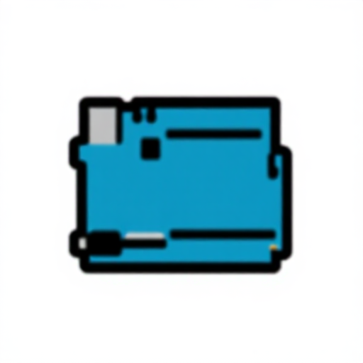 Prototyping Shield for Arduino Uno (3-Pack)
 Arduino Uno R3 BoardArduino Uno
 - Instead of 5mm LED Assortment Kit (300pcs, 5 Colors), try:
 WS2812B NeoPixel LED Strip (1m, 60 LEDs)
 Diffused LED - 10mm
 RGB LED Strip 5050 (5m, Non-Addressable)
 LilyPad Tri-Color LED
 SMD LED 0603 - Strip of 25
 LilyPad LED - 5 pcs
 - Instead of Push Button - 33mm, try:
 Concave Retro Gaming Button
 Toggle & Duffle Coat Button Set
 - Instead of Resistor 330 Ohm 1/6 Watt PTH - 20 pack, try:
 AVR ISP Shield - PTH Kit
Recommended for this build
Products makers often use with builds like this one.
 LED - RGB Diffused Common Cathode - 5mmFrequently used with this build's materials
 Diode KitFrequently used with this build's materials
 Piezo ElementUsed together and in similar builds
 Jumper Wire Kit (350pcs, M-M / M-F / F-F)Frequently used with this build's materials
 Servo MotorFrequently used with this build's materials
 USB CableFrequently used with this build's materials
 PotentiometerUsed together and in similar builds
Related blueprints
Other builds that share materials, tools, or techniques with this one.


CC0 Domínio Público
Este blueprint é liberado sob CC0. Você é livre para copiar, modificar, distribuir e usar este trabalho para qualquer finalidade, sem pedir permissão.
Apoie o Maker comprando produtos através do Blueprint, onde ele ganha uma Comissão Maker definida pelos vendedores, ou crie uma nova versão deste Blueprint e inclua-o como conexão no seu próprio Blueprint para compartilhar receita.