
Using Relays — SIK Circuit 13
Instruções
Parts & Introduction
Parts & Introduction
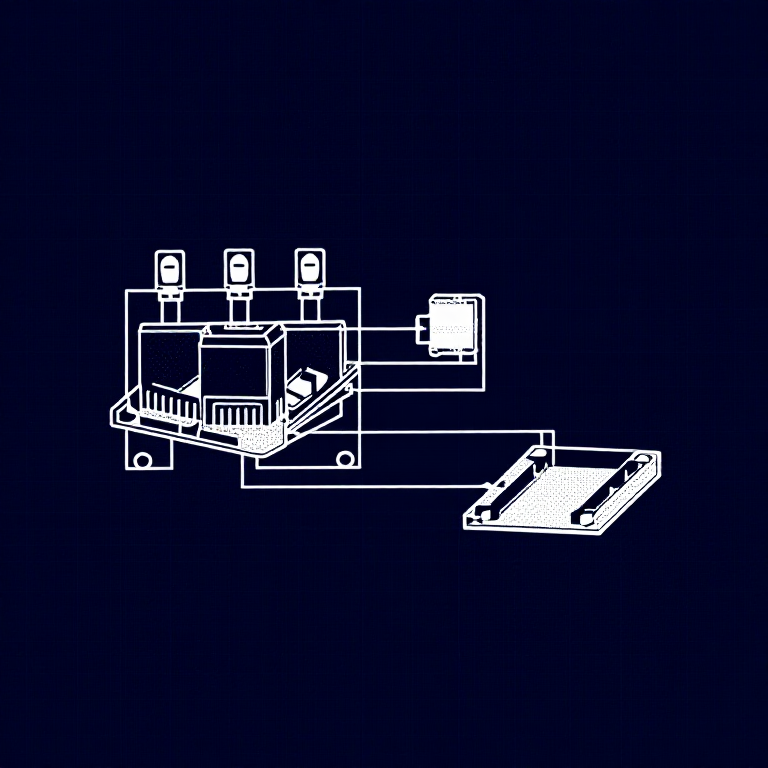
A relay is an electrically-operated mechanical switch. A small current energizes a coil that physically moves a contact arm, switching a separate circuit. Relays can control high-power devices (motors, lights, appliances) from low-power Arduino signals. This experiment uses an SPDT (Single Pole Double Throw) relay to alternate between two LEDs.
Parts Needed
- 1x Arduino Uno + USB cable
- 1x Breadboard
- 1x SPDT Relay
- 1x NPN Transistor (P2N2222A)
- 1x Diode (1N4148)
- 2x LEDs (different colors)
- 2x 330Ω Resistors
- 14x Jumper Wires
Materiais para este passo:
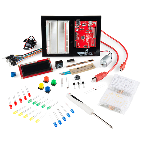 SparkFun Inventor's Kit - V3.21 kit
Ferramentas necessárias:
 Computador com o IDE Arduino
Hardware Hookup
Hardware Hookup
Wiring Instructions
Transistor + Relay Coil
- Connect transistor Base through 330Ω resistor to Arduino Digital Pin 2.
- Connect transistor Emitter to GND.
- Connect one side of the relay coil to transistor Collector.
- Connect other side of relay coil to 5V.
- Flyback Diode: Band (cathode) to 5V, anode to Collector.
Relay Contacts + LEDs
- Connect relay COMMON through a 330Ω resistor to 5V.
- Connect relay NC (Normally Closed) to LED 1 positive leg.
- Connect relay NO (Normally Open) to LED 2 positive leg.
- Connect both LED negative legs to GND.
Materiais para este passo:
 Relé SPDT1 peça
 Placa de ensaio1 peça
 Fios de ligação8 peças
Arduino Code
Arduino Code
Open the Arduino IDE and upload the following sketch to your Arduino board.
Materiais para este passo:
 Arduino Uno R31 peça
Ferramentas necessárias:
Computador com o IDE ArduinoTest & Experiment
Test & Experiment
What You Should See
You should hear the relay clicking, and see the two LEDs alternating — one on, one off — switching every second.
Troubleshooting
- LEDs not lighting: Check LED polarity — longer leg is positive.
- No clicking sound: The transistor or coil circuit isn't working. Verify transistor orientation and coil connections.
- Relay not making good contact: The SIK relay is designed for soldering, not breadboarding. Press it firmly to ensure all pins contact.
- Confusion: Don't mix up the TMP36 temperature sensor with the transistor!
Experiments to Try
- Replace the LEDs with a motor on the NO contact — use the relay as a motor on/off switch.
- Use a button to control when the relay toggles.
- Add variable delay to create morse code patterns.
Materiais
9- SparkFun Inventor's Kit - V3.210% de comissão1 kitR$521.92
- Referência
- Referência
- Referência
- 1 peçaReferência
- 1 peçaReferência
- 1 peçaReferência
- Referência
- 2 peçasReferência
Ferramentas necessárias
1- Referência
CC0 Domínio Público
Este blueprint é liberado sob CC0. Você é livre para copiar, modificar, distribuir e usar este trabalho para qualquer finalidade, sem pedir permissão.
Apoie o Maker comprando produtos através do Blueprint, onde ele ganha uma Comissão Maker definida pelos vendedores, ou crie uma nova versão deste Blueprint e inclua-o como conexão no seu próprio Blueprint para compartilhar receita.