Colaboração
ARTE
BELEZA E BEM-ESTAR
ARTESANATO
CULTURA E HISTÓRIA
ENTRETENIMENTO
MEIO AMBIENTE
COMIDA E BEBIDAS
ENGENHARIA REVERSA
CIÊNCIAS
ESPORTES
TECNOLOGIA
TECNOLOGIA VESTÍVEL
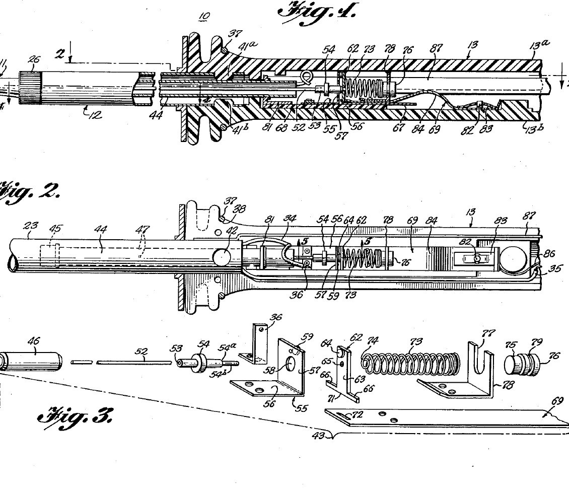


Soldering Iron: Temperature Controlled by a Curie-Point Tip and a Magnet Switch (Weller, US 3,188,448, 1965)
A soldering iron that holds its own tip temperature. At the back of the copper tip sits a slug of nickel-iron alloy that stops being magnetic above a set temperature (its Curie point). A small Alnico magnet behind it is pulled forward while the slug is cool, closing a switch that feeds the heater; once the tip is hot the slug lets go, a steel bushing pulls the magnet back and the switch opens. Swap tips to choose 600, 700 or 800 °F.
Result: a 55-watt temperature-controlled iron idling near 700 °F instead of running ever hotter.
Source: C. E. Weller, US 3,188,448 (1965). Unknown: the plating baths, the heater wire and insulation, most sizes. Picture: the patent drawing.
Avançado
Unknown
Instruções
1
1
Make the tip and control slug
Make the tip and control slug
Turn the tip from tellurium copper: a cylindrical body, a taper and a chisel end (any shape suits the work). Plate it first with iron, which keeps the copper out of the molten solder, then with nickel, which shuts out the air. Bore its rear end and fit tightly into it the shank of a slug of thermomagnetic nickel-iron alloy, such as 48 % nickel, 3 % molybdenum and the rest iron, or about 43 % nickel and the rest iron. The alloy sets the control point: make tips for 600, 700 and 800 °F. Not given: the plating baths, sizes.
Materiais para este passo:
 Barra de cobre-telúrio1 tip
 Liga termomagnética de níquel-ferro1 control slug
Ferramentas necessárias:
 Torno mecânico
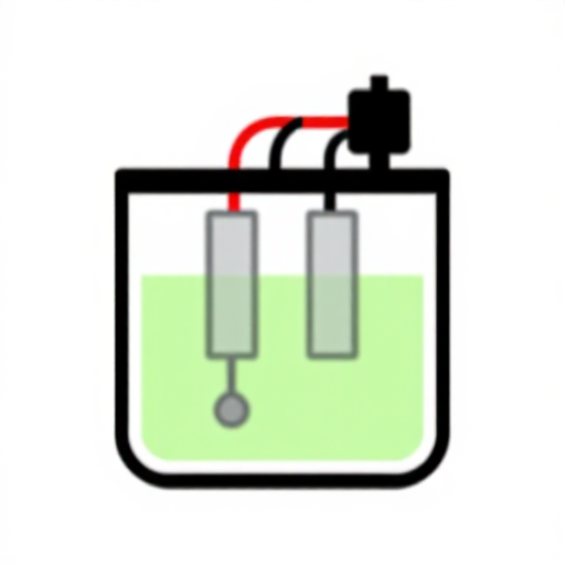 Kit de galvanoplastia
 Dimensões desconhecidas
2
2
Wind the heater barrel
Wind the heater barrel
Make the barrel of two stainless steel tubes: an inner spool the tip slides into snugly, and an outer cover tube joined to it at the front, with a thread and screw cap to hold the tip. In the space between them wind the heater from one length of resistance wire: an inner layer, then an outer layer wound the opposite way so their fields cancel, with insulating sheet inside, between and outside the layers. Silver-solder heat-resistant leads to its ends. Ours: nichrome wire. Not given: the insulating sheet, the turns.
Materiais para este passo:
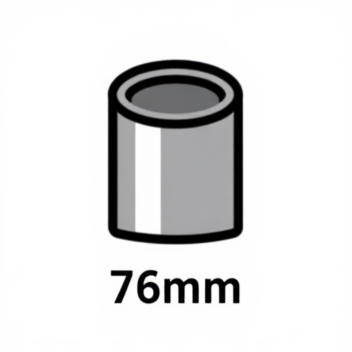 Tubo de aço inoxidável2 spool and cover tube
 Fio de nicrómio1 heater
 Material isolante desconhecido1 three sheet layers
 Metal desconhecido1 leads
 Solda de prata1 as needed
Ferramentas necessárias:
 Maçarico a propanoTorno mecânico
3
3
Build the magnet switch
Build the magnet switch
In a stainless steel sleeve about 2.4 in long, close the front with a non-magnetic thermal bushing. Behind it slides a cylindrical Alnico V magnet, then a non-magnetic spacer about 0.032 in thick, then a cold-drawn steel bushing about 0.50 in long held by dents in the sleeve; the magnet's stroke is about 0.015 in. A push rod runs from the magnet through the bushing to an insulator. On a melamine plate, hinge a moving contact between a thin conducting strip and a holding strip, facing a flexible contact; a spring of fourteen coils of 0.010 in music wire, 0.210 in across, presses the moving contact toward the flexible one. Rivet the spring bracket to the holding strip. Not given: the contact metals.
Materiais para este passo:
Tubo de aço inoxidável1 sleeve Íman de Alnico1 peça
 Varão de aço macio1 magnetic bushing, push rodMetal desconhecido1 thermal bushing, spacer, contacts, strips, brackets
 Material desconhecido1 insulator
 Placa de melamina1 base plate
 Fio de aço para molas1 0.010 in music wire spring
Ferramentas necessárias:
Torno mecânico Jogo de rebitar
 Alicate de bicos redondos
4
4
Assemble the handle and use
Assemble the handle and use
Mould the handle in two plastic halves with a socket at the front whose bosses lock the cover tube. Lay in the switch unit, held only by the bowed tail of its holding strip on an anchor pin with a speed nut, so it floats and its thermal bushing presses on the tip's slug. Wire the heater, the switch and a ground lead from the cover tube to the cord. Rivet the halves near the butt and fit a split ring near the front. In use, below the control point the slug pulls the magnet forward and the spring closes the contacts; above it the steel bushing pulls the magnet back and the push rod opens them. At idle the heater runs only about 30 to 40 % of the time. Not given: the plastic.
Materiais para este passo:
Material desconhecido1 handle halvesMetal desconhecido1 rivet, split ring, speed nut Cabo flexível com ficha1 peça
Ferramentas necessárias:
 Máquina de moldação por injeçãoJogo de rebitar
Materiais
13- Referência
- 1 control slugReferência
- 1 sleeveReferência
- 1 heaterReferência
- 1 three sheet layersReferência
- 1 rivet, split ring, speed nutReferência
- 1 as neededReferência
- 1 peçaReferência
- 1 magnetic bushing, push rodReferência
- 1 handle halvesReferência
- 1 base plateReferência
- 1 0.010 in music wire springReferência
- 1 peçaReferência
Ferramentas necessárias
7- Referência
- Referência
- Referência
- Referência
- Referência
- Referência
- Referência
Materiais de Blueprints conectados

Este projeto faz

CC0 Domínio Público
Este blueprint é liberado sob CC0. Você é livre para copiar, modificar, distribuir e usar este trabalho para qualquer finalidade, sem pedir permissão.
Apoie o Maker comprando produtos através do Blueprint, onde ele ganha uma Comissão Maker definida pelos vendedores, ou crie uma nova versão deste Blueprint e inclua-o como conexão no seu próprio Blueprint para compartilhar receita.