ARTE
BELEZA E BEM-ESTAR
ARTESANATO
CULTURA E HISTÓRIA
ENTRETENIMENTO
MEIO AMBIENTE
COMIDA E BEBIDAS
ENGENHARIA REVERSA
CIÊNCIAS
ESPORTES
TECNOLOGIA
TECNOLOGIA VESTÍVEL
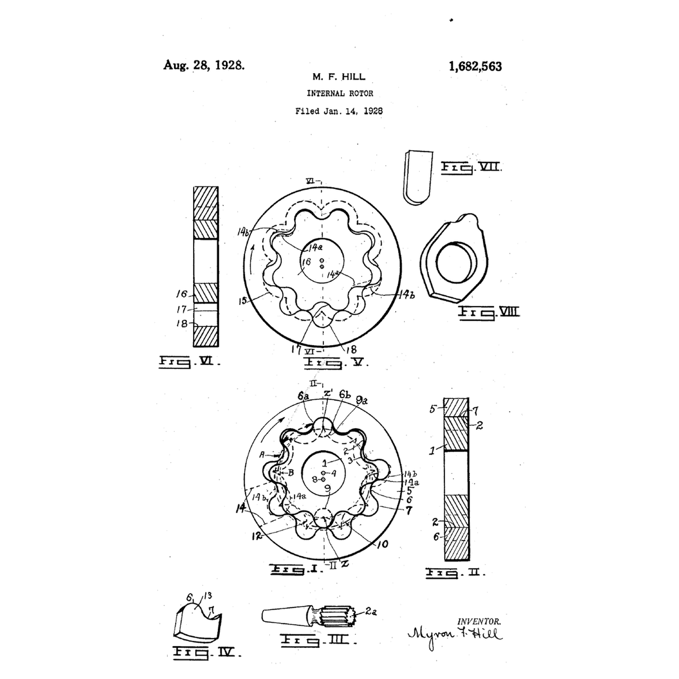


The Gerotor: Two Rotors, One Tooth Apart
A gear pump needs two shafts and a housing shaped round both gears. The gerotor puts one rotor inside the other on offset centres: the inner rotor has one tooth fewer than the outer, every tooth of each stays in sliding contact with the other, and the spaces between them open on one side and close on the other as both turn. It is small, quiet and cheap, and it pumps the oil in most car engines.
Myron F. Hill of New York worked out how to generate the tooth shapes: roll two circles together in the ratio of the tooth numbers and trace one rotor's tooth to find the other's contour. US 1,682,563, *Internal Rotor*, divided from an application of 5 November 1921, was filed 14 January 1928 and granted 28 August 1928. He coined the name — GE-nerated ROTOR.
This rung generates a nine-and-eight gerotor by Hill's method, finds the pin size that undercuts, computes its displacement, and 3D-prints it as a working pump.
Avançado
About 6 hours
Instruções
1
1
Generate, check and size a gerotor
Generate, check and size a gerotor
A carregar o notebook Jupyter…
2
2
Read Hill's rolling circles
Read Hill's rolling circles
The patent defines the rotors by construction, not by formula: "Let two circles be located upon a plane, one within the other and tangent to it. Let their diameters be in proportion to the numbers of tooth divisions selected for the two rotors which should differ by one." A master curve for one rotor's tooth is rolled round with its circle and "traced in each successive position"; the curve along the crests of the traces is the other rotor's contour. "This inner circle may rotate nine times while the outer circle rotates eight times", in inverse proportion to the numbers of teeth.
Hill also describes making them this way: a master tool revolved round one pitch circle cuts a blank turning at the proportional speed about the other, generating the rotor exactly as the notebook does in numbers.
3
3
The external gear pump it improves on
The external gear pump it improves on
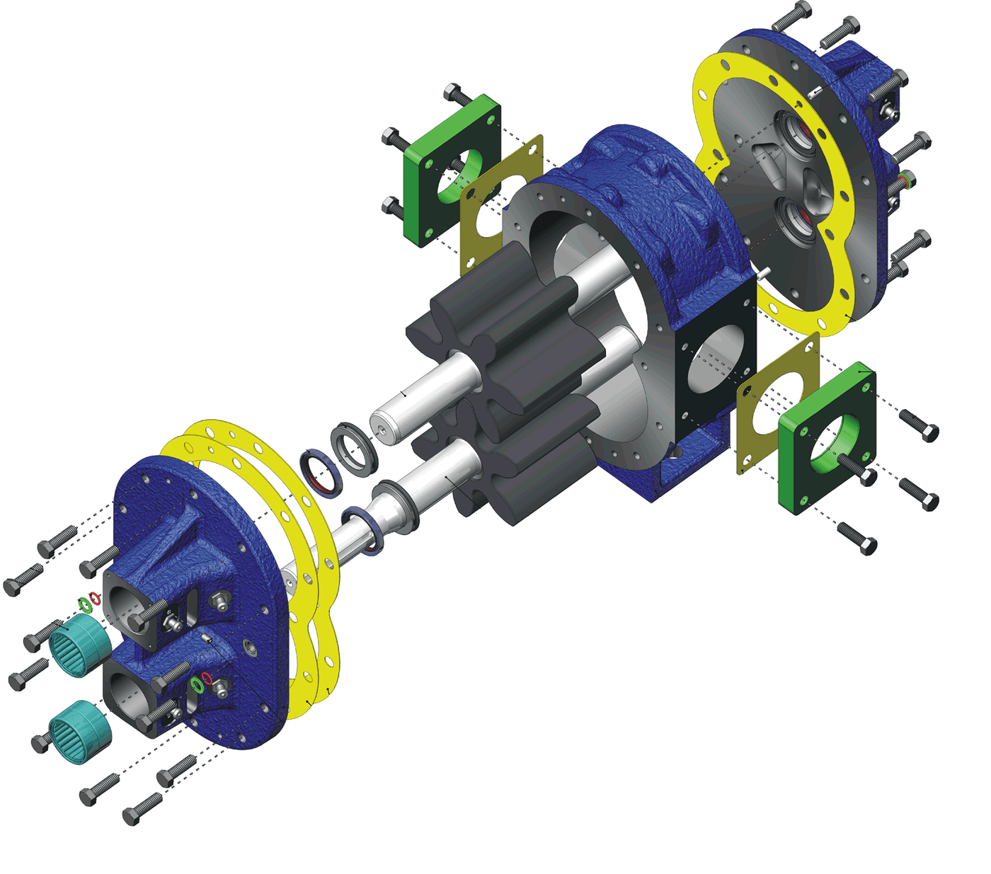
The gerotor does the external gear pump's job with one shaft and a round housing. The embedded blueprint shows how meshing teeth carry oil round the outside.
4
4
Print a working gerotor pump
Print a working gerotor pump
Add a line to the notebook that prints the inner profile's coordinates, and save them as a CSV. Import them into your CAD program as a spline and extrude 10 mm: that is the inner rotor, bored for an 8 mm steel shaft. Draw the outer rotor as a ring with nine 4 mm half-round teeth on a 20 mm radius, 10 mm thick, turning in a round pocket in a printed housing whose centre is 2 mm off the shaft's.
Cut a kidney-shaped inlet port on the side where the chambers grow and an outlet where they shrink, in a clear acrylic cover plate with an O-ring round the pocket. Print the rotors in PETG at fine layer height and sand the faces flat on glass.
Drive the shaft with a cordless drill, inlet in a jug of water, outlet into a graduated cylinder. Count revolutions with a tachometer and compare the water delivered per revolution with the notebook. The printed set leaks at its faces, so expect less; the difference is its volumetric efficiency.
Materiais para este passo:
 Bomba gerotor1 peça
 Barra de aço em bruto1 peça
 Chapa de acrílico1 peça
 Sortido de anéis de vedação1 peça
 Parafusos de máquina8 peças
 Água2 litros
Ferramentas necessárias:
 Impressora 3D de filamento (FDM)
 Filamento PETG
 Berbequim sem fios
 Tacómetro digital
 Proveta graduada
 Jarro medidor
 Sortido de lixa
 Paquímetro digital de 6 polegadas
5
5
A gerotor pump that has lost its prime or its pressure
A gerotor pump that has lost its prime or its pressure
Gerotor faults are mostly about clearances and the inlet.
Flow
Loading...
6
6
History and context
History and context
**Myron F. Hill** of New York filed his first gerotor applications in 1921; **US 1,682,563**, *Internal Rotor*, divided from the application of 5 November 1921, was filed 14 January 1928 and granted 28 August 1928. He published *Kinematics of Gerotors* in 1927. With toolmaker **William H. Nichols** he built machines to make the rotor sets; the first commercial use was in oil-burner pumps in the 1930s. Gerotors, many of them pressed from powdered metal, now pump oil in engines and automatic transmissions.
**Honest limits.** The notebook's area is counted on a grid and each chamber is split at the pin centre-lines, so its displacement is good to a few per cent, not exact. Printed rotors leak far more than ground metal ones. And gerotors suit moderate pressures; high pressure circuits use piston pumps.
Materiais
6- 1 peçaReferência
- 1 peçaReferência
- 1 peçaReferência
- Referência
- 8 peçasReferência
- 2 litrosReferência
Ferramentas necessárias
8- Referência
- Referência
- 1 vendor sell this, none ship to you yetReferência
- Referência
- Referência
- Referência
- Referência
- Referência
Blueprints relacionados
Estes blueprints compartilham conhecimento — técnicas, materiais ou princípios


CC0 Domínio Público
Este blueprint é liberado sob CC0. Você é livre para copiar, modificar, distribuir e usar este trabalho para qualquer finalidade, sem pedir permissão.
Apoie o Maker comprando produtos através do Blueprint, onde ele ganha uma Comissão Maker definida pelos vendedores, ou crie uma nova versão deste Blueprint e inclua-o como conexão no seu próprio Blueprint para compartilhar receita.