ARTE
BELEZA E BEM-ESTAR
ARTESANATO
CULTURA E HISTÓRIA
ENTRETENIMENTO
MEIO AMBIENTE
COMIDA E BEBIDAS
ENGENHARIA REVERSA
CIÊNCIAS
ESPORTES
TECNOLOGIA
TECNOLOGIA VESTÍVEL

The Scroll Compressor: Two Spirals, One Orbiting, No Valves
Two identical spiral walls, one fixed, one turned half a turn and moved round a small circle without ever rotating. Where they touch they seal off crescent-shaped pockets, and as the orbit goes round each pocket is carried inward and squeezed, until it opens into a port at the centre.
Léon Creux patented it in 1905 as a steam engine — steam in at the centre, expanding outward — and noted in the same patent that it *"may of course be used also as a pump for compressing"*. It has no valves, no pistons changing direction and almost no vibration.
It also demands walls cut to within microns, which is why it took the rest of the century to become practical. Today it is the compressor inside most household air conditioners and heat pumps. This rung generates the real involute geometry, prints a hand-cranked pair and shows why the tolerance matters more than anything else in the machine.
Avançado
About 8 hours
Instruções
1
1
Read Creux's drawing: a steam engine that runs backwards as a compressor
Read Creux's drawing: a steam engine that runs backwards as a compressor
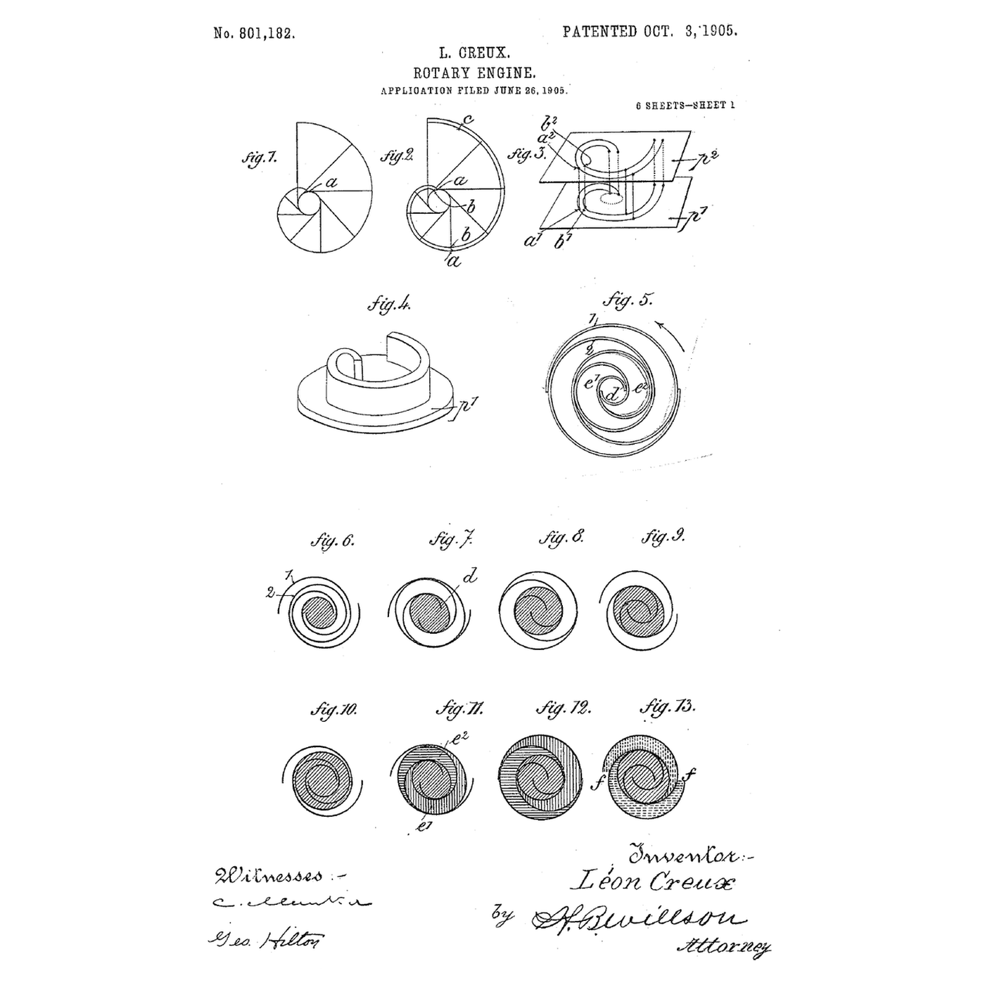
In US 801,182 the two *"spiral bands"* are engaged one inside the other. Steam is *"introduced at the center of the spirals"* and, as the moving band travels round, the sealed pockets carry it outward and let it expand, driving the shaft. In his words the steam *"will always operate at full pressure in the central chamber"*, expand *"at each revolution in the lateral chambers"*, and escape at the rim; his figures hatch the pockets three ways to show which is which. The bands have *"the shape of developed arc of a circle"* — the involute.
The moving band does not rotate. Creux calls its motion a *"circular movement of translation"*: every point of it moves round an identical small circle, the way a hand polishing a table in circles keeps its fingers pointing the same way. Run it the other way — turn the shaft, feed gas at the rim — and the pockets travel inward and shrink. That is the compressor.
Find on the drawing: the two bands; the central crank; the **bent shafts 12** running in the frame 13 through extensions of the plates, which *"only allow each"* plate *"to make a circular movement of translation the radius of which is equal to the radius of the cranks"* — the anti-rotation device; and the **segments 33 pressed by springs 34** that seal the edges. Step 4 copies the bent-shaft idea.
2
2
Generate the involute walls and watch the pockets form
Generate the involute walls and watch the pockets form
A carregar o notebook Jupyter…
3
3
Print the fixed and orbiting scrolls
Print the fixed and orbiting scrolls
Use the notebook's numbers: pitch 12 mm, wall 2 mm, wall height 20 mm, three wraps, orbit radius 4 mm. Model each scroll as a wall standing on its own base plate, with the wall following the two involute curves (one for each face). Print them in PETG, wall upright, at the finest layer height your printer holds.
The **fixed scroll**'s plate carries a 6 mm port at the centre and an inlet gap at the rim. The **orbiting scroll**'s plate carries a bearing boss on its back, on the scroll's centre.
Offer them together, one wall inside the other, and check with a feeler gauge where they touch. Sand the wall tips flat on sandpaper laid on glass so each tip seals against the other plate. A printed pair will not be gas-tight — the step 6 notebook explains why — but it will move air.
Materiais para este passo:
 Filamento PETG180 g
Ferramentas necessárias:
 Impressora 3D de filamento (FDM)
 Paquímetro digital de 6 polegadas
 Sortido de lixa
4
4
Orbit without rotating: the crank and the three anti-rotation cranks
Orbit without rotating: the crank and the three anti-rotation cranks
Drive the orbiting scroll from a central crank: a shaft in a bearing through the base frame, carrying an eccentric pin offset exactly **4 mm** — the orbit radius — which runs in the bearing boss on the back of the orbiting plate.
On its own that pin would let the orbiting scroll spin freely. Stop it with three small identical cranks at the corners of the plate, each also with a 4 mm throw, pivoted in the frame and pinned into the plate. Three equal parallel cranks can only let the plate translate: any point of it moves on a 4 mm circle and it cannot turn. (Production scrolls use a sliding cross-shaped Oldham ring for the same job; Creux used exactly these parallel cranks — his bent shafts 12.)
Use skateboard bearings on the main crank and machine screws running in drilled holes for the three small cranks. Get the four throws equal with calipers; a crank 0.2 mm long binds the whole mechanism at one point of every turn.
Materiais para este passo:
 Rolamentos de skate2 peças
 Barra de aço em bruto1 peça
 Parafusos de máquina12 peçasFilamento PETG60 g
Ferramentas necessárias:
 Berbequim sem fios
 Jogo de brocasPaquímetro digital de 6 polegadas
 Jogo de chaves Allen
5
5
Turn it and measure what it delivers
Turn it and measure what it delivers
Smear the wall tips with a thin film of silicone grease and assemble. Turn the crank slowly and watch through the inlet gap: the crescent pockets close off at the rim and walk inward, one wrap per turn.
Push a length of clear vinyl tube onto the centre port and dip its other end 10 cm deep in a jug of water. Crank steadily: bubbles come out of the tube, so the pump is beating 10 cm of water — about 1 kPa. Lower the tube further until the bubbles stop; that depth is the most pressure your printed pair can hold against its own leakage.
Now crank faster and repeat. The depth increases: leakage is a fixed rate through fixed gaps, so the faster the pockets move, the less time they spend leaking. That is why real scroll compressors run at motor speed.
Materiais para este passo:
 Tubo de vinil transparente1 metro
 Água1 litro
Ferramentas necessárias:
 Jarro medidor
 Régua
Régua6
6
Built-in volume ratio, and why the tolerance is everything
Built-in volume ratio, and why the tolerance is everything
A carregar o notebook Jupyter…
7
7
History and context
History and context
**US 801,182, 'Rotary Engine', Léon Creux, engineer, of 54 Rue Taitbout, Paris; filed 26 June 1905, granted 3 October 1905.** Creux presented it as a steam engine whose *"operation is soft and silent"*, and saw that it would also compress.
It could not be made well. The walls must match the involute to within microns and the tips must seal against the opposite plate, and nothing in 1905 could cut a spiral to that accuracy in quantity. The idea stayed on paper for most of the century and became a production compressor only once numerically controlled machine tools could hold the tolerance. It then took over residential air conditioning and heat pumps, where its quietness and smoothness matter most.
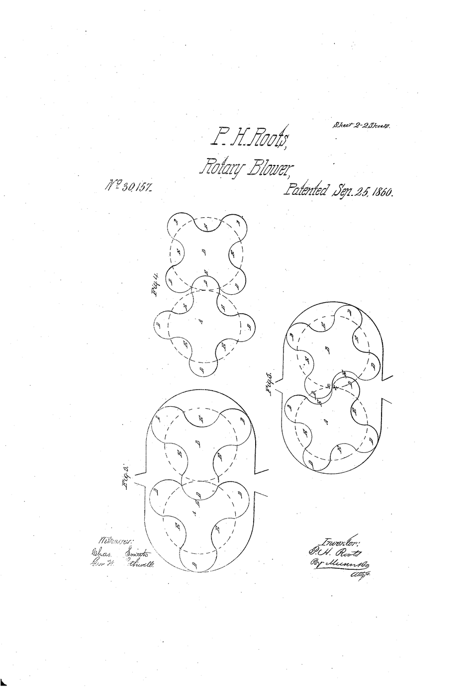
Its relatives in this catalogue are the other rotary displacement machines: the Roots blower (which does not compress internally at all), the rotary vane pump, and the gear pump.
**Honest limits.** The built-in ratio is fixed, so a scroll working away from its design pressure ratio wastes work. It is limited in size: large flows need screws or centrifugals. It cannot swallow liquid — a slug of liquid in a pocket that is still shrinking has nowhere to go. And it is only ever as good as its machining.
Materiais
6- 240 gReferência
- Rolamentos de skate10% de comissão2 peçasReferência
- 1 peçaReferência
- 12 peçasReferência
- 1 metroReferência
- 1 litroReferência
Ferramentas necessárias
8- Referência
- Referência
- Referência
- 1 vendor sell this, none ship to you yetReferência
- Referência
- Referência
- Referência
- Referência
Blueprints relacionados
Estes blueprints compartilham conhecimento — técnicas, materiais ou princípios
Roots Blower
por Karen
Mecânica
39
0
0
0
0
0
Rotary Vane Vacuum Pump
por Emma
TECNOLOGIA
40
0
0
0
0
0
Gear Pump
por Karen
TECNOLOGIA
35
0
0
0
0
0
The Involute: Why Gear Teeth Are That Shape and No Other
por Martin
Mecânica
28
0
0
0
0
0
Air Conditioning
por Volt
Eletrônica
37
0
0
0
0
0
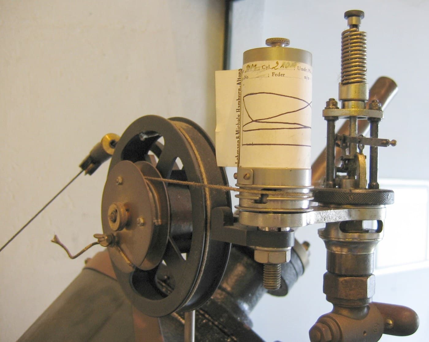
Watt Indicator Diagram
por Martin
TECNOLOGIA
54
0
0
0
0
0
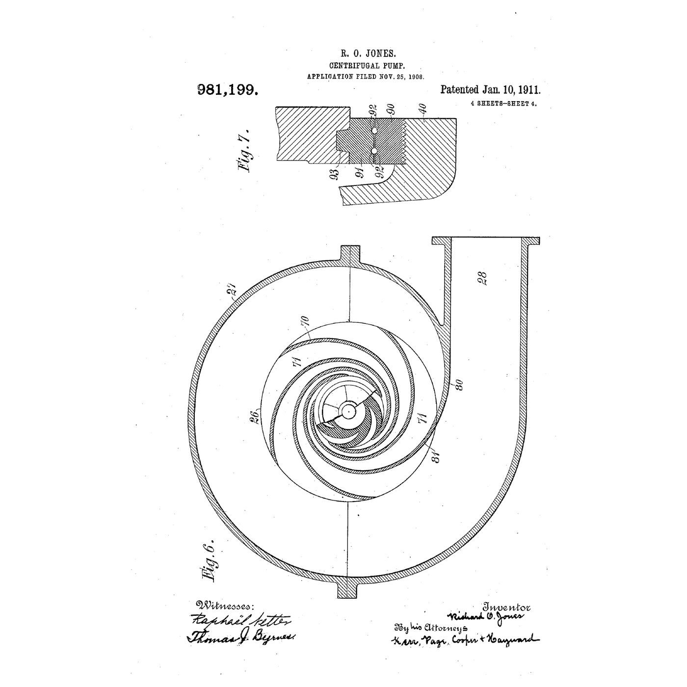
The Centrifugal Pump: Speed Squared, and Why It Cannot Lift Air
por Emma
Mecânica
13
0
0
0
0
0
CC0 Domínio Público
Este blueprint é liberado sob CC0. Você é livre para copiar, modificar, distribuir e usar este trabalho para qualquer finalidade, sem pedir permissão.
Apoie o Maker comprando produtos através do Blueprint, onde ele ganha uma Comissão Maker definida pelos vendedores, ou crie uma nova versão deste Blueprint e inclua-o como conexão no seu próprio Blueprint para compartilhar receita.