སྒྱུ་རྩལ
མཛེས་སྡུག་དང་བདེ་ཐང
བཟོ་རིག
རིག་གནས་དང་ལོ་རྒྱུས
དགའ་སྟོན
ཁོར་ཡུག
ཟས་དང་བཏུང་རྫས
ཕྱིར་འཕྲུལ་རིག
ཚན་རིག
རྩེད་འགྲན
རིག་རྩལ
གྱོན་རུང
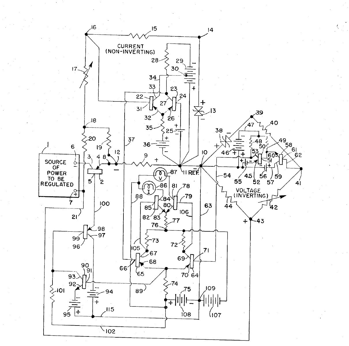


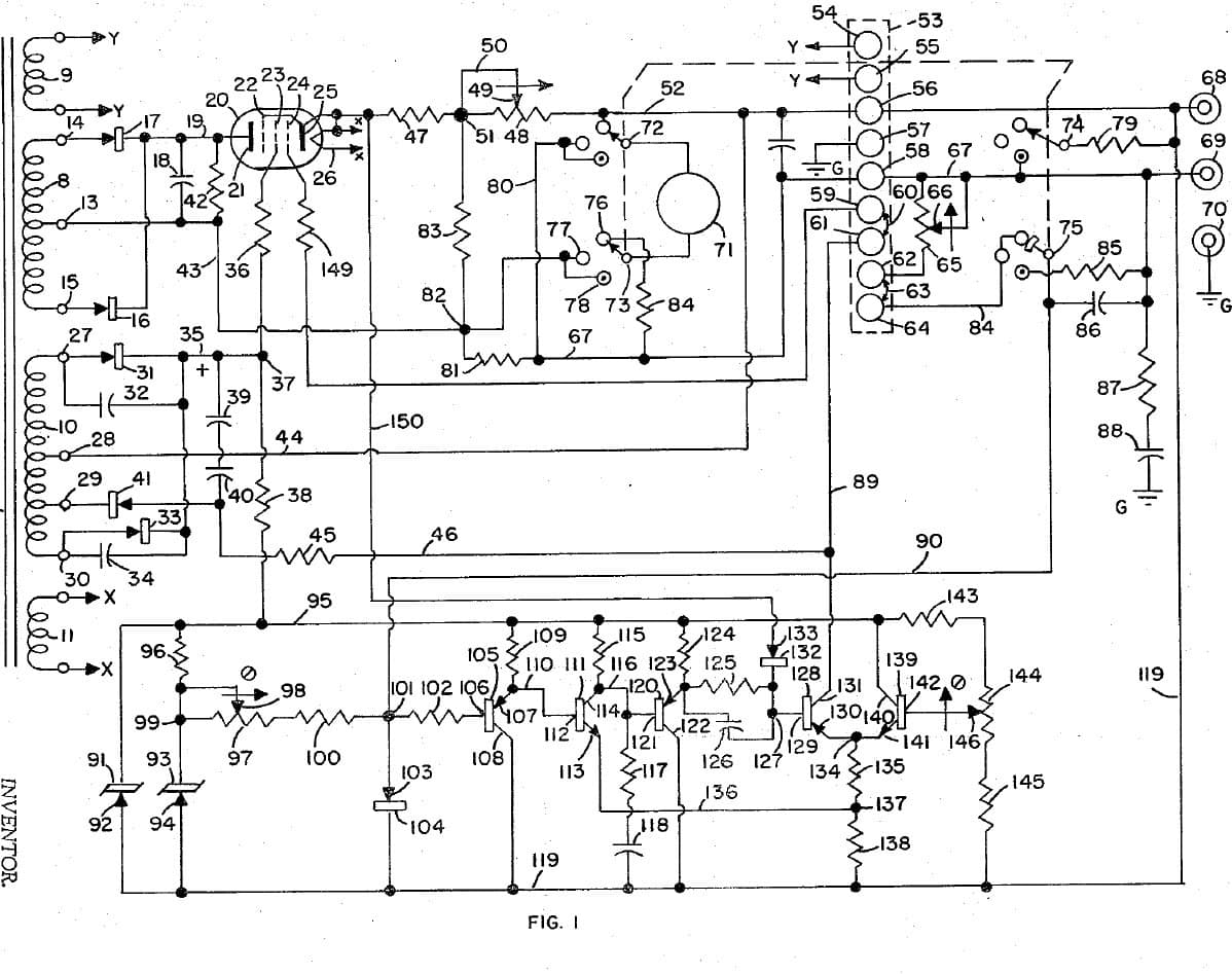
Adjustable Bench Power Supply: Constant Voltage / Constant Current with Cross-Over Lamps (Gately, Forbro, US 3,303,411, 1967)
An all-transistor bench supply with two knobs: one sets the voltage, the other the current. It holds the set voltage until the load tries to draw more than the set current, then switches at once to holding the current, and back again, with no in-between state. Two lamps show which mode is in control.
Result: an adjustable constant-voltage / constant-current DC supply with mode lamps.
Source: J. R. Gately (Forbro Design), US 3,303,411 (1967). Unknown: all component values and ratings. Builds on the same inventor's 1966 current-limited supply. Picture: the patent drawing.
མཐོ་རིམ
Unknown
ལམ་སྟོན
1
1
Build the raw supplies
Build the raw supplies
In a case, wire the cord through a switch and fuse to two power transformers, each with rectifiers and a filter: one gives the main power to be regulated, the other the bias supplies, held steady by Zener diodes. Not given: the voltages. Ours: the case, switch and fuse.
གོམ་པ་འདིའི་རྫས་རིགས:
 ཨ་ལུ་མི་ནིཡམ་གྱི་སྒྲོམ།1 དུམ་བུ།
 ཕལག་ཡོད་པའི་ གློག་སྐུད་ལྷབ་ལྷབ།1 དུམ་བུ།
 འཕར་སྒུལ་སྒོ་ལྕགས།1 དུམ་བུ།
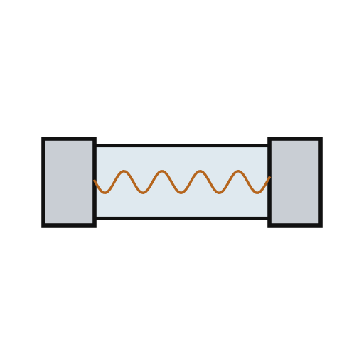 ཞུ་ཐིག།1 དུམ་བུ།
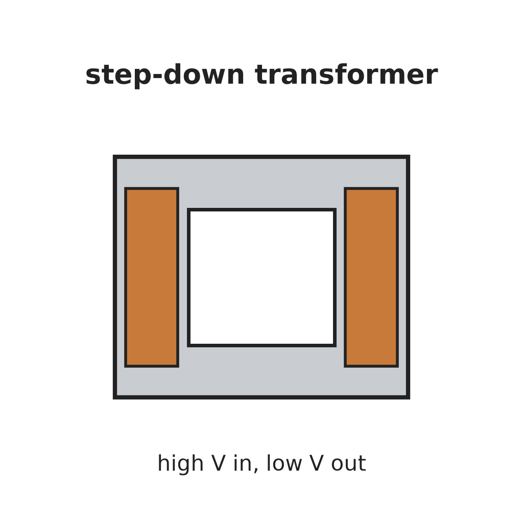 གློག་ཤུགས་འབབ་བཏང་གི་ཊྲཱནས་ཕོར་མར2 དུམ་བུ།
 ཌའི་ཨོཌ།6 rectifiers
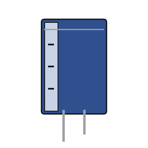 གློག་ཞུན་ ཀེ་པེ་སི་ཊར།3 filters
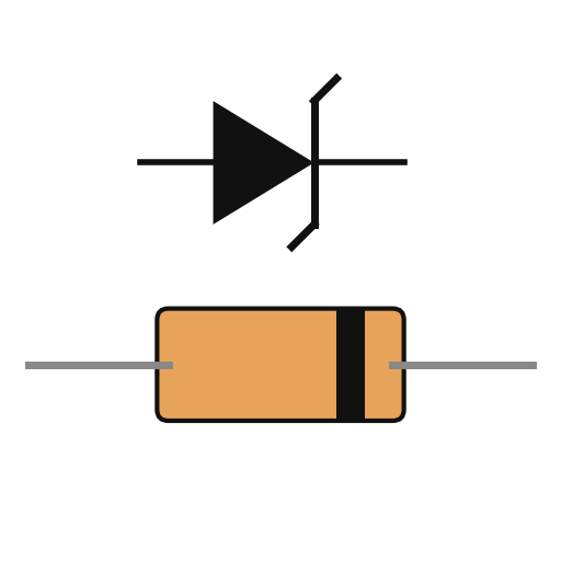 ཛི་ནར་ཌའི་ཡོཌ།2 bias
ལག་ཆས་དགོས་མཁོ:
 ལག་འཕྲུལ་ཁུང་བཏོན
 སྒྲོག་བསྐོར་ཆས་ཆ་ཚང་།
2
2
Fit the pass transistor and current bridge
Fit the pass transistor and current bridge
Put a power transistor on a heat sink in series with the output: collector to the negative supply, emitter through a current-sensing resistor to the negative output terminal. Make the current bridge from the sensing resistor, a reference Zener, a reference resistor and the adjustable current-control resistor: the output current is proportional to its setting. A small trimming resistor sets the maximum current. Not given: the values.
གོམ་པ་འདིའི་རྫས་རིགས:
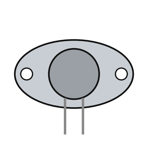 ནུས་ཤུགས་ ཊཱན་སི་སི་ཊར།1 series pass
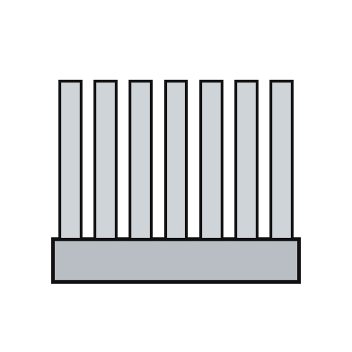 དྲོད་ཕྱིར་བཏང་ཆས།1 དུམ་བུ།ཛི་ནར་ཌའི་ཡོཌ།1 current reference
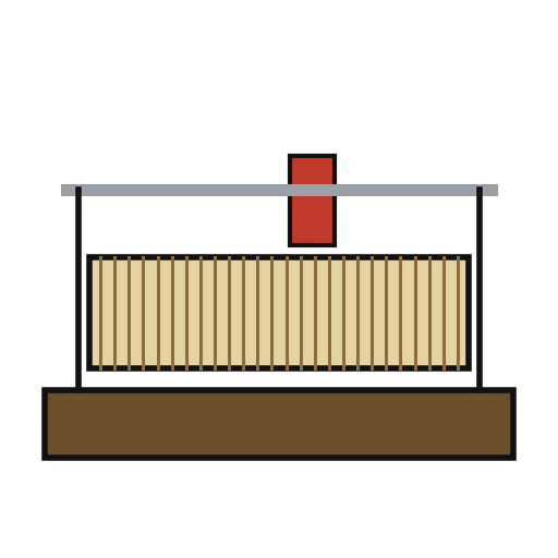 རི་ཡོ་སི་ཊེཊ།1 current control
 འགོག་ཤུགས།1 sensing, reference, trim set
 མཐུད་ཀ་བ།2 output + and -
ལག་ཆས་དགོས་མཁོ:
 ཞ་བཏབ་ནིའི་ལྕགས།
3
3
Build the voltage bridge
Build the voltage bridge
Make the voltage bridge from a reference Zener, a reference resistor, the adjustable voltage-control resistor and the load itself across the output. A small trimming resistor sets the maximum voltage. Add two resistors that feed the current bridge enough extra to cover the voltage bridge's own current and any voltmeter across the output, so low currents are still held exactly.
གོམ་པ་འདིའི་རྫས་རིགས:
ཛི་ནར་ཌའི་ཡོཌ།1 voltage referenceརི་ཡོ་སི་ཊེཊ།1 voltage controlའགོག་ཤུགས།1 reference, trim, compensation setལག་ཆས་དགོས་མཁོ:
ཞ་བཏབ་ནིའི་ལྕགས།4
4
Build the amplifiers and cross-over
Build the amplifiers and cross-over
Give each bridge an error amplifier. Feed the two amplified errors to the bases of a pair of transistors sharing one emitter resistor: whichever base is the more negative takes control and cuts the other off, so the supply is always cleanly in voltage mode or current mode. Amplify the shared emitter signal through two more transistors to drive the pass transistor's base. Add an emitter-follower clamp on the bias line. Not given: the transistor types.
གོམ་པ་འདིའི་རྫས་རིགས:
 PCB ལེབ1 དུམ་བུ།
 ཊརཱན་སིསི་ཊར་སྣ་ཚོགས།1 error amplifiers, cross-over pair, drivers, clampའགོག་ཤུགས།1 ཚན་པ།
 པོ་ཊེན་ཤོ་མི་ཊར།1 clamp divider
 ཞ་སྦྱར་རྫས་ཀྱི་སྐུད་པ1 as needed
ལག་ཆས་དགོས་མཁོ:
ཞ་བཏབ་ནིའི་ལྕགས།5
5
Fit the mode lamps and use it
Fit the mode lamps and use it
From the cross-over pair, drive two lamp transistors, each lighting one lamp: one for voltage mode, one for current mode. In use, set the voltage and the current limit. With a light load the voltage lamp is lit and the voltage holds; if the load tries to draw more than the set current, the supply switches to holding the current and the current lamp lights.
གོམ་པ་འདིའི་རྫས་རིགས:
ཊརཱན་སིསི་ཊར་སྣ་ཚོགས།1 two lamp drivers གློག་མེའི་རྐང་སྟེགས།2 དུམ་བུ།
 གློག་མེ་ཤེལ་སྒོང་།2 དུམ་བུ།
ལག་ཆས་དགོས་མཁོ:
སྒྲོག་བསྐོར་ཆས་ཆ་ཚང་།རྫས་རིགས
19- 1 དུམ་བུ།ས་ཆ་འཛིན
- 1 དུམ་བུ།ས་ཆ་འཛིན
- ས་ཆ་འཛིན
- 1 དུམ་བུ།ས་ཆ་འཛིན
- 2 དུམ་བུ།ས་ཆ་འཛིན
- 6 rectifiersས་ཆ་འཛིན
- 3 filtersས་ཆ་འཛིན
- 1 voltage referenceས་ཆ་འཛིན
- 1 series passས་ཆ་འཛིན
- 1 དུམ་བུ།ས་ཆ་འཛིན
- 1 voltage controlས་ཆ་འཛིན
- 1 ཚན་པ།ས་ཆ་འཛིན
- ས་ཆ་འཛིན
- 1 དུམ་བུ།ས་ཆ་འཛིན
- 1 two lamp driversས་ཆ་འཛིན
- ས་ཆ་འཛིན
- 1 as neededས་ཆ་འཛིན
- 2 དུམ་བུ།ས་ཆ་འཛིན
- 2 དུམ་བུ།ས་ཆ་འཛིན
ལག་ཆས་དགོས་མཁོ
3- ས་ཆ་འཛིན
- ས་ཆ་འཛིན
- 2 vendors sell this, none ship to you yetས་ཆ་འཛིན
བིལུ་པིརིན་ཊི་འདི་གིས་བཟོ་མི

འབྲེལ་ཡོད་བིལུ་པིརིན་ཊི
བིལུ་པིརིན་ཊི་འདི་ཚུ་ཐབས་ལམ་དང་རྫས་རིགས། སྤྱི་ཆོས་བགོ་བཤའ་བྱེད
CC0 སྤྱི་དབང
བིལུ་པིརིན་ཊི་འདི་CC0 འོག་བཀྲམས་ཡོད། ཁྱེད་རང་གིས་ཆོག་མཆན་མ་བཞེས་པར་ཕབ་ལེན་དང་བཟོ་བཅོས། བགོ་བཤའ། དགོས་མཁོ་གང་ལའང་བཀོལ་སྤྱོད་བྱས་ཆོག
བཟོ་མཁན་ལ་རྒྱབ་སྐྱོར་བྱེད་པའི་ཆེད་ཁོང་ཚོའི་བིལུ་པིརིན་ཊི་བརྒྱུད་ཐོན་སྐྱེད་ཉོ། བཟོ་མཁན་གྱིས བཟོ་མཁན་གྱི་ཁེ་ཕོགས ཚོང་པས་གཏན་འཁེལ་བྱས་པ། ཡང་ན་བིལུ་པིརིན་ཊི་འདིའི་པར་གསར་བཟོས་ཏེ་ཁྱེད་རང་གི་བིལུ་པིརིན་ཊི་ནང་མཐུད་སྦྲེལ་བྱས་ཏེ་ཡོང་སྒོ་བགོ་བཤའ་བྱེད།