སྒྱུ་རྩལ
མཛེས་སྡུག་དང་བདེ་ཐང
བཟོ་རིག
རིག་གནས་དང་ལོ་རྒྱུས
དགའ་སྟོན
ཁོར་ཡུག
ཟས་དང་བཏུང་རྫས
ཕྱིར་འཕྲུལ་རིག
ཚན་རིག
རྩེད་འགྲན
རིག་རྩལ
གྱོན་རུང
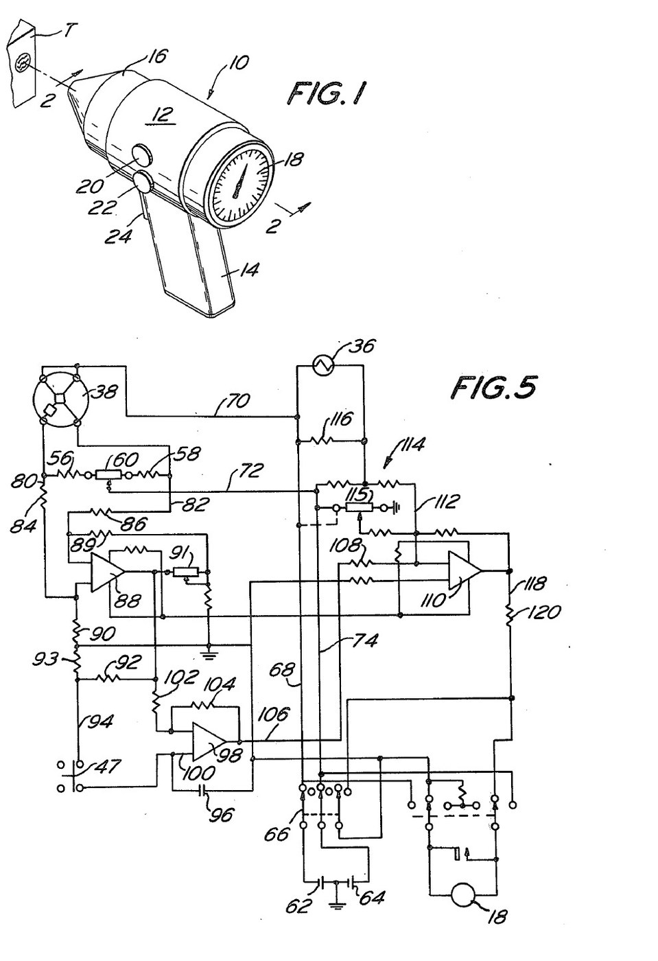


Infrared Thermometer: Pistol Grip with a Trigger-Swung Mirror That Zeroes on the Cavity (Michael, US 4,005,605, 1977)
A pistol-grip thermometer that reads a surface's temperature from its infrared radiation, without touching it. Inside, a concave mirror on a pivot first looks at the instrument's own cavity and a thermistor there, so the circuit stores a zero; pulling the trigger swings the mirror to the nose opening and focuses the target's radiation on a thermistor bolometer. The meter shows the difference, corrected for the cavity's temperature.
Result: a non-contact thermometer reading -20 to 60 °C, built for veterinary use.
Source: D. S. Michael (Mikron Instrument), US 4,005,605 (1977). Unknown: sizes, component values and most materials. Picture: the patent drawing.
མཐོ་རིམ
Unknown
ལམ་སྟོན
1
1
Build the housing and nose
Build the housing and nose
Make a housing with a pistol handle, in three pieces for easy assembly. Fix a cone-shaped nose to its front, cut off at the tip to leave a round opening about one tenth of the cavity's inside diameter, so little stray radiation gets in or out. Paint the inside of the nose and cavity flat black. An infrared-transparent sheet may close the nose to keep out dirt and draughts. Not given: sizes, the materials.
གོམ་པ་འདིའི་རྫས་རིགས:
 ངོ་མ་ཤེས་པའི་རྒྱུ་ཆ།1 housing, nose, window
 ཚོན་ནག་མི་འཚེར་བ།1 as needed
ལག་ཆས་དགོས་མཁོ:
 ཚོན་པིར་ཡངས་ཏོག་ཏོ།
 མ་ཤེས་པའི་ཚད།
2
2
Fit the detector, mirror and ambient thermistor
Fit the detector, mirror and ambient thermistor
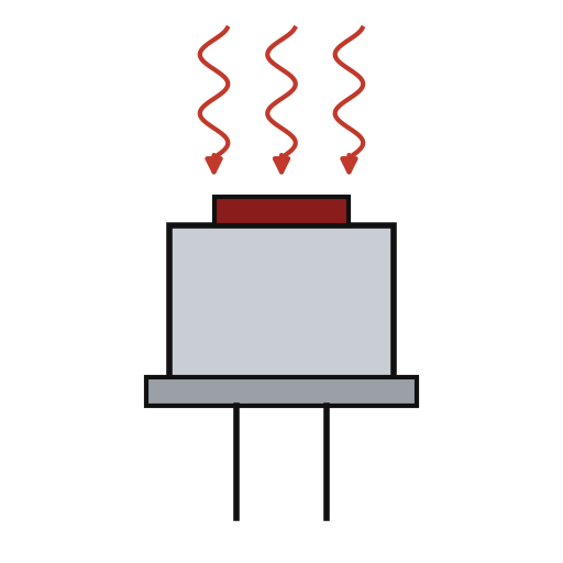
Hold the thermistor bolometer on the housing's axis with a spider. Mount a concave mirror in a gimbal ring on two trunnions in bearings in the housing wall, with the detector at its focus when it faces the nose. Put a bead thermistor inside the cone. A leaf spring holds the ring tilted so the mirror faces the thermistor. Not given: the mirror's focal length, the metals.
གོམ་པ་འདིའི་རྫས་རིགས:
 ཐར་མིས་ཊར་བོ་ལོ་མི་ཊར།1 དུམ་བུ།
 ནང་གུག་གི་མེ་ལོང་།1 དུམ་བུ།
 མ་ཤེས་པའི་ལྕགས་རིགས།1 gimbal ring, trunnions, spider
 NTC ཐར་མིསི་ཊར་གྱི་ཆ་ཚང་1 bead thermistor
 ལྕགས་ལེབ་སི་པིརིང་།1 དུམ་བུ།
ལག་ཆས་དགོས་མཁོ:
 སྒྲོག་བསྐོར་ཆས་ཆ་ཚང་།མ་ཤེས་པའི་ཚད།
3
3
Fit the trigger
Fit the trigger
Pivot a trigger in the handle. A finger on it pushes the gimbal ring against the spring, so the mirror turns to face the nose opening, and at the same moment opens a small switch beside the trigger. Fit the off-on switch and two control knobs on the housing, and the meter in its back. Ours: a microswitch and a moving-coil meter.
གོམ་པ་འདིའི་རྫས་རིགས:
མ་ཤེས་པའི་ལྕགས་རིགས།1 trigger, finger, pivot ཕྲ་རབ་སྒོ་ལྕགས།1 དུམ་བུ།
 འཕར་སྒུལ་སྒོ་ལྕགས།1 multipole off-on
 འགུལ་བའི་གློག་འཁྱིལ་ཅན་གྱི་པེ་ནཱལ་འཇལ་ཆས།1 དུམ་བུ།
ལག་ཆས་དགོས་མཁོ:
སྒྲོག་བསྐོར་ཆས་ཆ་ཚང་།4
4
Wire the circuit and measure
Wire the circuit and measure
Wire the bolometer's active and passive elements as two arms of a Wheatstone bridge, with two resistors and a balancing potentiometer as the others; batteries in the handle feed it through the off-on switch. The bridge feeds a differential preamplifier with a gain potentiometer. Through the trigger switch its output charges a capacitor on the + input of a FET-input op-amp whose input bias current is under 1 pA; match the divider resistors to the op-amp's resistors within 0.1 %. Feed that op-amp's output into a summing amplifier together with an ambient correction from the bead thermistor (a fixed resistor across it, and a potentiometer to set the starting reading), and drive the meter from the sum. To use, switch on and balance the bridge; with the trigger released the mirror faces the cavity and the capacitor stores that reading. Aim at the target and pull the trigger: the meter shows the target minus the stored cavity reading, plus the ambient correction, so detector and preamplifier drift cancel. Not given: the component values.
གོམ་པ་འདིའི་རྫས་རིགས:
 PCB ལེབ1 དུམ་བུ།
 ཨོཔ་ཨེམ་པི་ IC3 preamplifier, FET-input store, summing
 འགོག་ཤུགས།1 set, incl. 0.1 % matched pairs
 པོ་ཊེན་ཤོ་མི་ཊར།4 དུམ་བུ།
 ཀོན་ཌེན་སར་ཆ་ཚན།1 storage capacitor
 གློག་སྨན་2 དུམ་བུ།
 ཞ་སྦྱར་རྫས་ཀྱི་སྐུད་པ1 as needed
ལག་ཆས་དགོས་མཁོ:
 ཞ་བཏབ་ནིའི་ལྕགས།
རྫས་རིགས
17- 1 housing, nose, windowས་ཆ་འཛིན
- 1 as neededས་ཆ་འཛིན
- 1 དུམ་བུ།ས་ཆ་འཛིན
- 1 དུམ་བུ།ས་ཆ་འཛིན
- 1 trigger, finger, pivotས་ཆ་འཛིན
- 1 bead thermistorས་ཆ་འཛིན
- 1 དུམ་བུ།ས་ཆ་འཛིན
- ས་ཆ་འཛིན
- ས་ཆ་འཛིན
- ས་ཆ་འཛིན
- 1 དུམ་བུ།ས་ཆ་འཛིན
- 3 preamplifier, FET-input store, summingས་ཆ་འཛིན
- 1 set, incl. 0.1 % matched pairsས་ཆ་འཛིན
- ས་ཆ་འཛིན
- 1 storage capacitorས་ཆ་འཛིན
- 2 དུམ་བུ།ས་ཆ་འཛིན
- 1 as neededས་ཆ་འཛིན
ལག་ཆས་དགོས་མཁོ
4- ས་ཆ་འཛིན
- ས་ཆ་འཛིན
- ས་ཆ་འཛིན
- 2 vendors sell this, none ship to you yetས་ཆ་འཛིན
མཐུད་སྦྲེལ་བིལུ་པིརིན་ཊི་རྫས་རིགས

བིལུ་པིརིན་ཊི་འདི་གིས་བཟོ་མི

CC0 སྤྱི་དབང
བིལུ་པིརིན་ཊི་འདི་CC0 འོག་བཀྲམས་ཡོད། ཁྱེད་རང་གིས་ཆོག་མཆན་མ་བཞེས་པར་ཕབ་ལེན་དང་བཟོ་བཅོས། བགོ་བཤའ། དགོས་མཁོ་གང་ལའང་བཀོལ་སྤྱོད་བྱས་ཆོག
བཟོ་མཁན་ལ་རྒྱབ་སྐྱོར་བྱེད་པའི་ཆེད་ཁོང་ཚོའི་བིལུ་པིརིན་ཊི་བརྒྱུད་ཐོན་སྐྱེད་ཉོ། བཟོ་མཁན་གྱིས བཟོ་མཁན་གྱི་ཁེ་ཕོགས ཚོང་པས་གཏན་འཁེལ་བྱས་པ། ཡང་ན་བིལུ་པིརིན་ཊི་འདིའི་པར་གསར་བཟོས་ཏེ་ཁྱེད་རང་གི་བིལུ་པིརིན་ཊི་ནང་མཐུད་སྦྲེལ་བྱས་ཏེ་ཡོང་སྒོ་བགོ་བཤའ་བྱེད།