སྒྱུ་རྩལ
མཛེས་སྡུག་དང་བདེ་ཐང
བཟོ་རིག
རིག་གནས་དང་ལོ་རྒྱུས
དགའ་སྟོན
ཁོར་ཡུག
ཟས་དང་བཏུང་རྫས
ཕྱིར་འཕྲུལ་རིག
ཚན་རིག
རྩེད་འགྲན
རིག་རྩལ
གྱོན་རུང
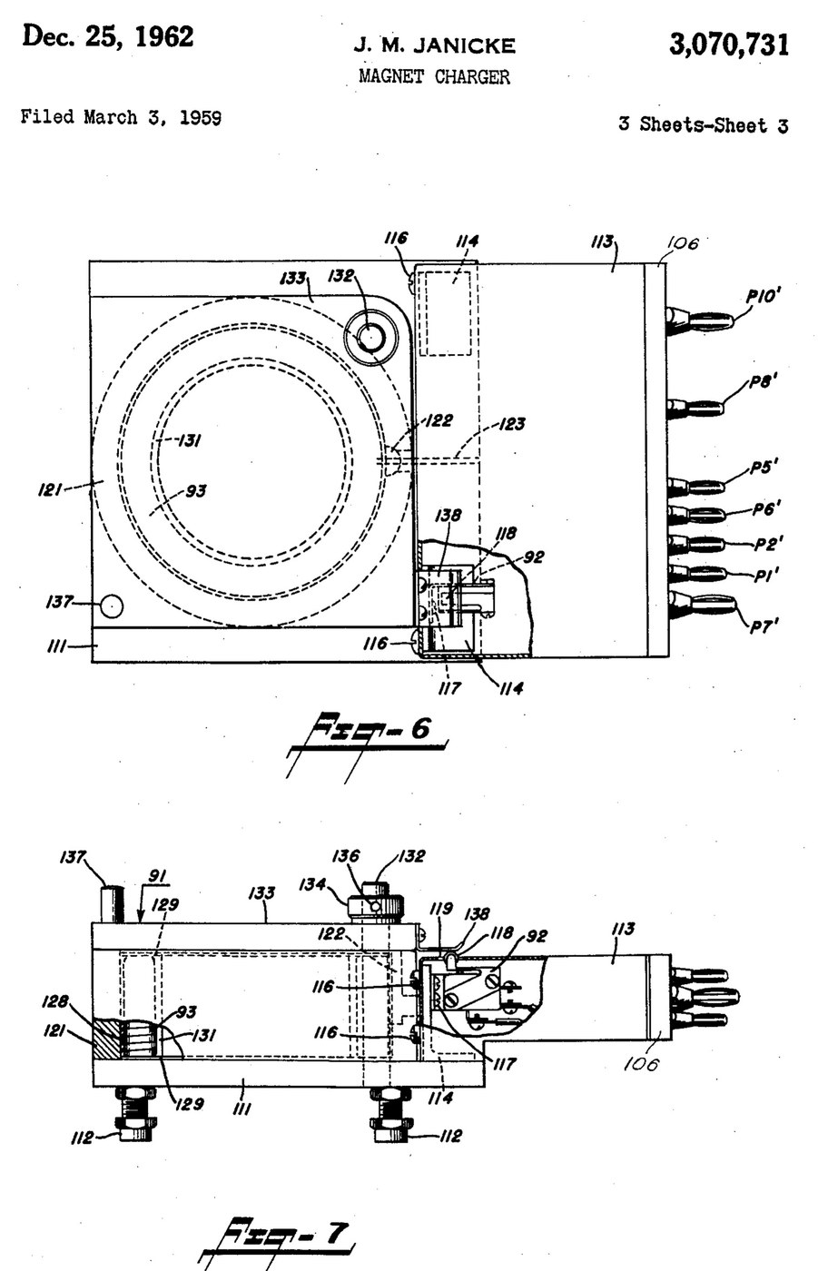


Magnetiser: Capacitor-Discharge Magnet Charger with a Wire-Wound Fixture (Janicke, US 3,070,731, 1962)
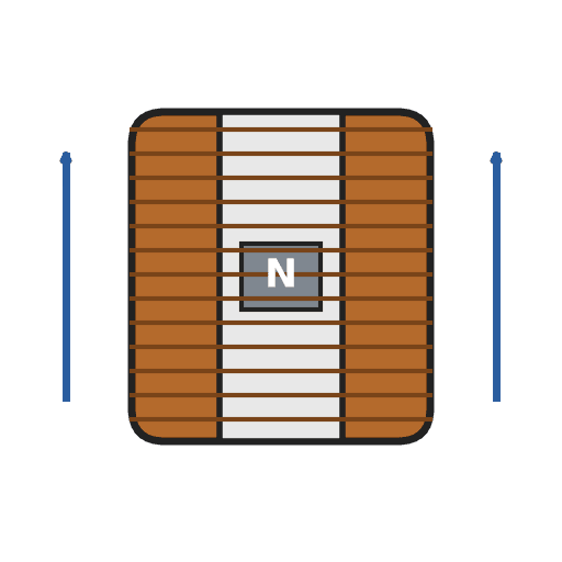
An impulse magnetiser. A capacitor is charged to a high voltage, then an ignitron dumps it all at once through a coil. The magnet sits inside the coil in a closed steel pot, so almost all of the flux goes through it.
Result: a magnet charger that magnetises rods, bars and blocks in one pulse, with an interlocked lid.
Source: J. M. Janicke, US 3,070,731 (1962). Unknown: voltages, capacitance, coil windings, field strength and sizes. Picture: the patent drawing.
ཆེས་མཁས་པ
Unknown
ལམ་སྟོན
1
1
Build the charging supply
Build the charging supply
Feed a line switch from the mains through two fuses, with a pilot lamp. Wire a high-voltage transformer with two primaries, which a high-low switch puts in series or in parallel. Run its centre-tapped secondary to two mercury-vapour rectifier tubes, "or the like", with their own filament transformer, so they charge the energy-storage capacitor. A charging on-off switch with a red lamp switches the high-voltage side. A meter with multiplier resistors across the capacitor shows its voltage. Ours: toggle switches, neon lamps, a moving-coil meter. Not given: any voltage or value.
གོམ་པ་འདིའི་རྫས་རིགས:
 ཝོལཊི་མཐོ་བའི་ བསྒྱུར་འཕྲུལ།1 high-voltage transformer
 དངུལ་ཆུའི་རླངས་པའི་ གློག་རྒྱུན་ཕྱོགས་གཅིག་བཟོ་བའི་དོང་པོ།2 rectifier tubes
 གློག་ཤུགས་འབབ་བཏང་གི་ཊྲཱནས་ཕོར་མར1 filament transformer
 ནུས་ཤུགས་བསག་པའི་ གློག་བསག་ཆས།1 storage capacitor
 འགུལ་བའི་གློག་འཁྱིལ་ཅན་གྱི་པེ་ནཱལ་འཇལ་ཆས།1 voltage meter
 ངོ་མ་ཤེས་པའི་ བཀག་ཆས།2 meter multipliers
 འཕར་སྒུལ་སྒོ་ལྕགས།3 line, charging and high-low switches
 ཞུ་ཐིག།2 fuses
 ནེ་ཨོན་བརྡ་སྟོན་གློག་མེ།2 pilot and red lamps
ལག་ཆས་དགོས་མཁོ:
 ཞ་བཏབ་ནིའི་ལྕགས།
 ལྕགས་སྐུད་ཀྱི་ཤུབས་བཤུས་ཆས།
2
2
Add the delay and the bleeder
Add the delay and the bleeder
Put a thermal time-delay relay before the charging switch: about thirty seconds after switch-on it energises a control relay, which feeds the charging switch and holds itself on. A third contact of the control relay lifts a bleeder resistor off the capacitor while the charger runs. When the charger is shut down the relay drops out and the bleeder drains the dangerous high-voltage charge from the capacitor.
གོམ་པ་འདིའི་རྫས་རིགས:
 དུས་ཚོད་འགྱངས་པའི་རི་ལེ།1 thermal delay relay
 རི་ལེ1 control relay, three contact setsངོ་མ་ཤེས་པའི་ བཀག་ཆས།1 bleeder resistor
ལག་ཆས་དགོས་མཁོ:
ཞ་བཏབ་ནིའི་ལྕགས།ལྕགས་སྐུད་ཀྱི་ཤུབས་བཤུས་ཆས།3
3
Fit the ignitron firing circuit
Fit the ignitron firing circuit
Put an ignitron in the discharge path of the storage capacitor, as its switch. The meter's multiplier resistors also form a divider that charges a small firing capacitor. Pressing the push button discharges the firing capacitor through a small limiting resistor into the ignitron's igniter, and the ignitron conducts. Not given: the firing capacitor's type and value.
གོམ་པ་འདིའི་རྫས་རིགས:
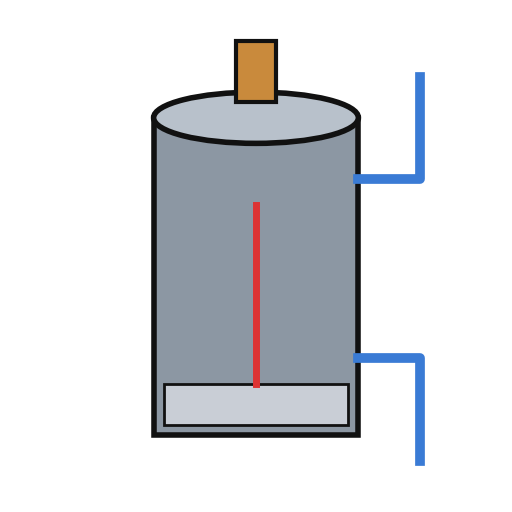 ཨིག་ནའི་ཊོན།1 discharge switch
 ངོ་མ་ཤེས་པའི་རྒྱུ་ཆ།1 firing capacitorངོ་མ་ཤེས་པའི་ བཀག་ཆས།1 limiting resistor
 གནོན་ཐེབས།1 charge button
ལག་ཆས་དགོས་མཁོ:
ཞ་བཏབ་ནིའི་ལྕགས།ལྕགས་སྐུད་ཀྱི་ཤུབས་བཤུས་ཆས།4
4
Build the wire-wound fixture
Build the wire-wound fixture
Weld a hollow cylindrical shell onto a base plate on levelling legs, both of magnetic material, to make a pot. Cut slots through the shell and the base plate so they cannot act as a shorted single-turn winding. Set the coil inside the shell in potting compound, with ring-shaped end pieces and a hollow cylindrical core in it. Hinge a square magnetic cover on a post beside the shell, held by a collar and set screw, with a handle. An L-shaped plate on the cover closes a switch in the igniter circuit only when the cover is shut. Wire the coil between the storage capacitor and the ignitron anode. Ours: mild steel, enamelled copper wire, casting epoxy. Not given: sizes, turns.
གོམ་པ་འདིའི་རྫས་རིགས:
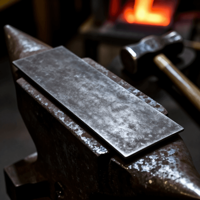
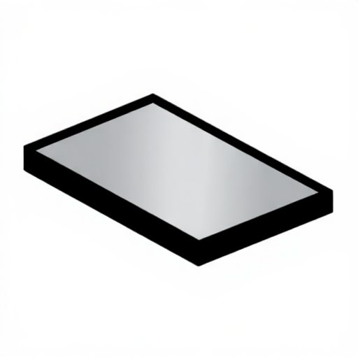 ལྕགས་འཇམ་གྱི་ཤོག་ལེབ་སྟུག།1 base plate and cover
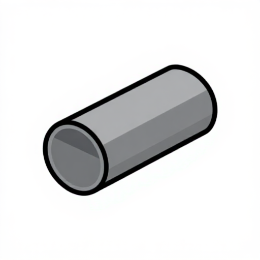 འཇམ་ལྕགས་ཀྱི་ཟླུམ་པའི་སྦུག་གུ1 shell
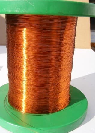
 ཨེ་ན་མཱེལ་བྱུགས་པའི་ཟངས་སྐུད།1 coil
 ནག་པོའི་བླུགས་ནིའི་ཨི་པོག་སི།1 potting compound
 མ་ཤེས་པའི་ལྕགས་རིགས།1 end pieces, core, post, legs
 ཕྲ་མཐེབ (མཐེབ་གཞོང་གིས་བསྐུལ་བ)1 lid interlock switch
ལག་ཆས་དགོས་མཁོ:
 ཨག་ཀི་གློག་འཕྲུལ་བཙག་འཕྲུལ།
 འཁོད་བཞག་ཕུག་འཕྲུལ།
 སྒྲོག་བསྐོར་ཆས་ཆ་ཚང་།
 མ་ཤེས་པའི་ཚད།
5
5
Charge a magnet
Charge a magnet
Put the magnet inside the core. Fill most of the air gap between it and the base plate and cover with soft iron, but leave a small gap near the cover, or the cover will be hard to swing open afterwards. Lay insulating material about 1/16 inch thick on top of the magnet. Close the cover, which arms the igniter switch, charge the capacitor, and press the button: one pulse magnetises it. Ours: wrought iron for the soft iron.
ལག་ཆས་དགོས་མཁོ:
 བརྡུངས་ལྕགས་ཀྱི་དབྱུག་ཏོ།
 མ་ཤེས་པའི་གློག་འགོག་རྒྱུ་ཆ།
རྫས་རིགས
20- 1 high-voltage transformerས་ཆ་འཛིན
- 2 rectifier tubesས་ཆ་འཛིན
- 1 filament transformerས་ཆ་འཛིན
- 1 storage capacitorས་ཆ་འཛིན
- 1 voltage meterས་ཆ་འཛིན
- 1 limiting resistorས་ཆ་འཛིན
- ས་ཆ་འཛིན
- 2 fusesས་ཆ་འཛིན
- 2 pilot and red lampsས་ཆ་འཛིན
- 1 thermal delay relayས་ཆ་འཛིན
- 1 control relay, three contact setsས་ཆ་འཛིན
- 1 discharge switchས་ཆ་འཛིན
- 1 firing capacitorས་ཆ་འཛིན
- ས་ཆ་འཛིན
- 1 base plate and coverས་ཆ་འཛིན
- ས་ཆ་འཛིན
- ས་ཆ་འཛིན
- 1 potting compoundས་ཆ་འཛིན
- 1 end pieces, core, post, legsས་ཆ་འཛིན
- 1 lid interlock switchས་ཆ་འཛིན
ལག་ཆས་དགོས་མཁོ
8- 2 vendors sell this, none ship to you yetས་ཆ་འཛིན
- ས་ཆ་འཛིན
- ས་ཆ་འཛིན
- ས་ཆ་འཛིན
- ས་ཆ་འཛིན
- ས་ཆ་འཛིན
- ས་ཆ་འཛིན
- ས་ཆ་འཛིན
མཐུད་སྦྲེལ་བིལུ་པིརིན་ཊི་རྫས་རིགས


བིལུ་པིརིན་ཊི་འདི་གིས་བཟོ་མི
CC0 སྤྱི་དབང
བིལུ་པིརིན་ཊི་འདི་CC0 འོག་བཀྲམས་ཡོད། ཁྱེད་རང་གིས་ཆོག་མཆན་མ་བཞེས་པར་ཕབ་ལེན་དང་བཟོ་བཅོས། བགོ་བཤའ། དགོས་མཁོ་གང་ལའང་བཀོལ་སྤྱོད་བྱས་ཆོག
བཟོ་མཁན་ལ་རྒྱབ་སྐྱོར་བྱེད་པའི་ཆེད་ཁོང་ཚོའི་བིལུ་པིརིན་ཊི་བརྒྱུད་ཐོན་སྐྱེད་ཉོ། བཟོ་མཁན་གྱིས བཟོ་མཁན་གྱི་ཁེ་ཕོགས ཚོང་པས་གཏན་འཁེལ་བྱས་པ། ཡང་ན་བིལུ་པིརིན་ཊི་འདིའི་པར་གསར་བཟོས་ཏེ་ཁྱེད་རང་གི་བིལུ་པིརིན་ཊི་ནང་མཐུད་སྦྲེལ་བྱས་ཏེ་ཡོང་སྒོ་བགོ་བཤའ་བྱེད།