སྒྱུ་རྩལ
མཛེས་སྡུག་དང་བདེ་ཐང
བཟོ་རིག
རིག་གནས་དང་ལོ་རྒྱུས
དགའ་སྟོན
ཁོར་ཡུག
ཟས་དང་བཏུང་རྫས
ཕྱིར་འཕྲུལ་རིག
ཚན་རིག
རྩེད་འགྲན
རིག་རྩལ
གྱོན་རུང
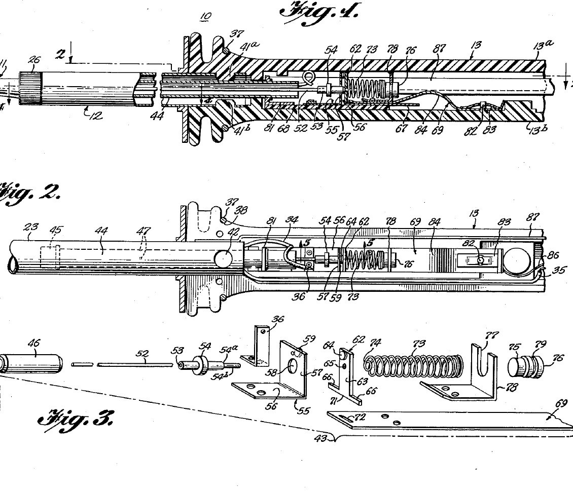


Soldering Iron: Temperature Controlled by a Curie-Point Tip and a Magnet Switch (Weller, US 3,188,448, 1965)
A soldering iron that holds its own tip temperature. At the back of the copper tip sits a slug of nickel-iron alloy that stops being magnetic above a set temperature (its Curie point). A small Alnico magnet behind it is pulled forward while the slug is cool, closing a switch that feeds the heater; once the tip is hot the slug lets go, a steel bushing pulls the magnet back and the switch opens. Swap tips to choose 600, 700 or 800 °F.
Result: a 55-watt temperature-controlled iron idling near 700 °F instead of running ever hotter.
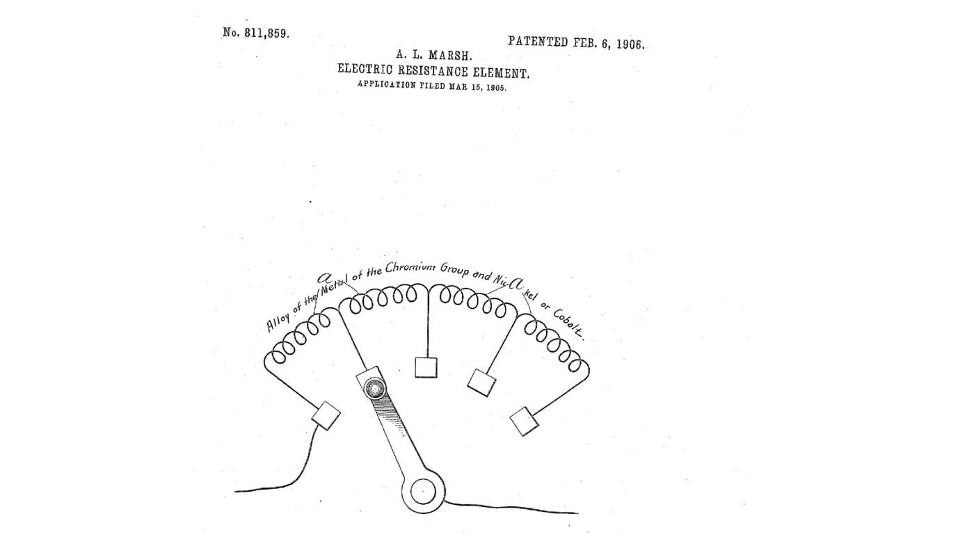
Source: C. E. Weller, US 3,188,448 (1965). Unknown: the plating baths, the heater wire and insulation, most sizes. Picture: the patent drawing.
མཐོ་རིམ
Unknown
ལམ་སྟོན
1
1
Make the tip and control slug
Make the tip and control slug
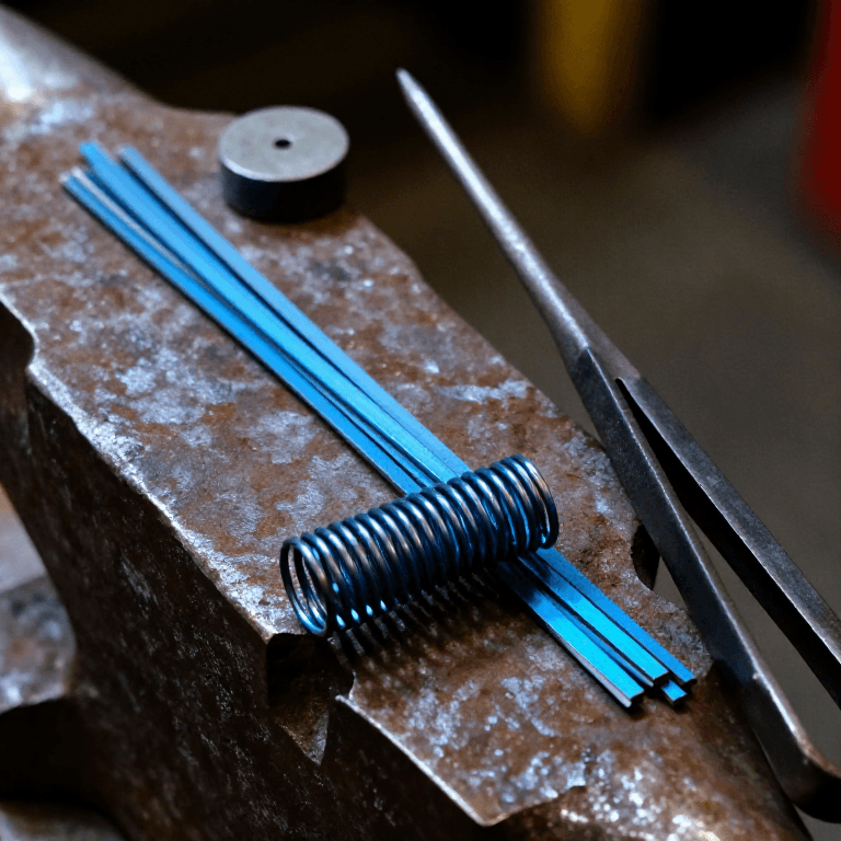
Turn the tip from tellurium copper: a cylindrical body, a taper and a chisel end (any shape suits the work). Plate it first with iron, which keeps the copper out of the molten solder, then with nickel, which shuts out the air. Bore its rear end and fit tightly into it the shank of a slug of thermomagnetic nickel-iron alloy, such as 48 % nickel, 3 % molybdenum and the rest iron, or about 43 % nickel and the rest iron. The alloy sets the control point: make tips for 600, 700 and 800 °F. Not given: the plating baths, sizes.
གོམ་པ་འདིའི་རྫས་རིགས:
 ཊེལ་ལུ་རི་ཡམ་ཟངས་ཀྱི་ཡུ་བ།1 tip
 དྲོད་ཁབ་ལེན་ ནི་ཀལ་-ལྕགས་ ལྷད་བསྲེས།1 control slug
ལག་ཆས་དགོས་མཁོ:
 ལྕགས་ཀྱི་འཁྲུལ་འཁོར།
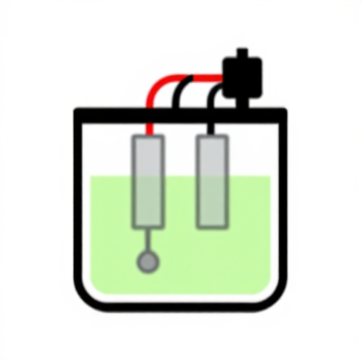 གློག་ཐོག་ལས་ལྕགས་བྱུགས་ནིའི་ཆ་ཚང་།
 མ་ཤེས་པའི་ཚད།
2
2
Wind the heater barrel
Wind the heater barrel
Make the barrel of two stainless steel tubes: an inner spool the tip slides into snugly, and an outer cover tube joined to it at the front, with a thread and screw cap to hold the tip. In the space between them wind the heater from one length of resistance wire: an inner layer, then an outer layer wound the opposite way so their fields cancel, with insulating sheet inside, between and outside the layers. Silver-solder heat-resistant leads to its ends. Ours: nichrome wire. Not given: the insulating sheet, the turns.
གོམ་པ་འདིའི་རྫས་རིགས:
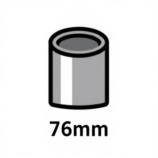 ཁ་ཟེ་མི་ཆགས་པའི་ལྕགས་སྦུག2 spool and cover tube
 ནའི་ཀོརོམ་གྱི་ལྕགས་སྐུད།1 heater
 མ་ཤེས་པའི་གློག་འགོག་རྒྱུ་ཆ།1 three sheet layers
 མ་ཤེས་པའི་ལྕགས་རིགས།1 leads
 དངུལ་གྱི་ཞ་སྦྱར་རྫས1 as needed
ལག་ཆས་དགོས་མཁོ:
 པོ་རོ་པེན་གྱི་མེ་ལྕེ།ལྕགས་ཀྱི་འཁྲུལ་འཁོར།
3
3
Build the magnet switch
Build the magnet switch
In a stainless steel sleeve about 2.4 in long, close the front with a non-magnetic thermal bushing. Behind it slides a cylindrical Alnico V magnet, then a non-magnetic spacer about 0.032 in thick, then a cold-drawn steel bushing about 0.50 in long held by dents in the sleeve; the magnet's stroke is about 0.015 in. A push rod runs from the magnet through the bushing to an insulator. On a melamine plate, hinge a moving contact between a thin conducting strip and a holding strip, facing a flexible contact; a spring of fourteen coils of 0.010 in music wire, 0.210 in across, presses the moving contact toward the flexible one. Rivet the spring bracket to the holding strip. Not given: the contact metals.
གོམ་པ་འདིའི་རྫས་རིགས:
ཁ་ཟེ་མི་ཆགས་པའི་ལྕགས་སྦུག1 sleeve ཨཱལ་ནི་ཀོ་ ཁབ་ལེན།1 དུམ་བུ།
 ལྕགས་འཇམ་གྱི་དབྱུག་ཟླུམ།1 magnetic bushing, push rodམ་ཤེས་པའི་ལྕགས་རིགས།1 thermal bushing, spacer, contacts, strips, brackets
 ངོ་མ་ཤེས་པའི་རྒྱུ་ཆ།1 insulator
 མེ་ལ་མཱའིན་ ལྡེབ།1 base plate
 སྤིང་ལྕགས་ཀྱི་སྐུད་པ།1 0.010 in music wire spring
ལག་ཆས་དགོས་མཁོ:
ལྕགས་ཀྱི་འཁྲུལ་འཁོར། ལྕགས་གཟེར་གྱི་ཚན་ཁག
 ཁ་སྒོར་གྱི་གཟེར་འཛིན།
4
4
Assemble the handle and use
Assemble the handle and use
Mould the handle in two plastic halves with a socket at the front whose bosses lock the cover tube. Lay in the switch unit, held only by the bowed tail of its holding strip on an anchor pin with a speed nut, so it floats and its thermal bushing presses on the tip's slug. Wire the heater, the switch and a ground lead from the cover tube to the cord. Rivet the halves near the butt and fit a split ring near the front. In use, below the control point the slug pulls the magnet forward and the spring closes the contacts; above it the steel bushing pulls the magnet back and the push rod opens them. At idle the heater runs only about 30 to 40 % of the time. Not given: the plastic.
གོམ་པ་འདིའི་རྫས་རིགས:
ངོ་མ་ཤེས་པའི་རྒྱུ་ཆ།1 handle halvesམ་ཤེས་པའི་ལྕགས་རིགས།1 rivet, split ring, speed nut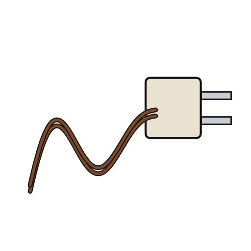 ཕལག་ཡོད་པའི་ གློག་སྐུད་ལྷབ་ལྷབ།1 དུམ་བུ།
ལག་ཆས་དགོས་མཁོ:
 བཙུགས་བཟོ་འཕྲུལ་ཆས།ལྕགས་གཟེར་གྱི་ཚན་ཁག
རྫས་རིགས
13- ས་ཆ་འཛིན
- 1 control slugས་ཆ་འཛིན
- 1 sleeveས་ཆ་འཛིན
- 1 heaterས་ཆ་འཛིན
- 1 three sheet layersས་ཆ་འཛིན
- 1 rivet, split ring, speed nutས་ཆ་འཛིན
- 1 as neededས་ཆ་འཛིན
- 1 དུམ་བུ།ས་ཆ་འཛིན
- 1 magnetic bushing, push rodས་ཆ་འཛིན
- 1 handle halvesས་ཆ་འཛིན
- 1 base plateས་ཆ་འཛིན
- 1 0.010 in music wire springས་ཆ་འཛིན
- 1 དུམ་བུ།ས་ཆ་འཛིན
ལག་ཆས་དགོས་མཁོ
7- ས་ཆ་འཛིན
- ས་ཆ་འཛིན
- ས་ཆ་འཛིན
- ས་ཆ་འཛིན
- ས་ཆ་འཛིན
- ས་ཆ་འཛིན
མཐུད་སྦྲེལ་བིལུ་པིརིན་ཊི་རྫས་རིགས

བིལུ་པིརིན་ཊི་འདི་གིས་བཟོ་མི

CC0 སྤྱི་དབང
བིལུ་པིརིན་ཊི་འདི་CC0 འོག་བཀྲམས་ཡོད། ཁྱེད་རང་གིས་ཆོག་མཆན་མ་བཞེས་པར་ཕབ་ལེན་དང་བཟོ་བཅོས། བགོ་བཤའ། དགོས་མཁོ་གང་ལའང་བཀོལ་སྤྱོད་བྱས་ཆོག
བཟོ་མཁན་ལ་རྒྱབ་སྐྱོར་བྱེད་པའི་ཆེད་ཁོང་ཚོའི་བིལུ་པིརིན་ཊི་བརྒྱུད་ཐོན་སྐྱེད་ཉོ། བཟོ་མཁན་གྱིས བཟོ་མཁན་གྱི་ཁེ་ཕོགས ཚོང་པས་གཏན་འཁེལ་བྱས་པ། ཡང་ན་བིལུ་པིརིན་ཊི་འདིའི་པར་གསར་བཟོས་ཏེ་ཁྱེད་རང་གི་བིལུ་པིརིན་ཊི་ནང་མཐུད་སྦྲེལ་བྱས་ཏེ་ཡོང་སྒོ་བགོ་བཤའ་བྱེད།