艺术
美容与健康
工艺
文化与历史
娱乐
环境
食品与饮料
逆向工程
科学
体育
技术
可穿戴设备
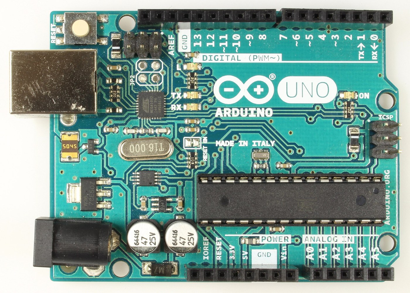


Arduino Uno R3: Assembled from Arduino's Open UNO-TH Rev3e Design Files and Flashed over ICSP
The Arduino Uno R3 is open hardware: Arduino publishes its schematic and board layout. This blueprint builds one from those files, part by part, then loads the firmware into its two processors.
Result: an Arduino Uno R3. An ATmega328P (16 MHz, 32 kB flash, 2 kB SRAM, 1 kB EEPROM) runs your programs; an ATmega16U2 turns USB into its serial link. It runs from USB (5.5 V at most) or 6-20 V at the DC jack.
Source: Arduino UNO-TH_Rev3e design files and the A000066 schematic and datasheet (Arduino, CC BY-SA). Unknown: how every bought part is made; no public source in hand says. The soldering method is ours. Picture: Wikimedia Commons.
高级
1 day
说明
1
1
Get the bare board
Get the bare board
Have the two-layer board made to Arduino's UNO-TH_Rev3e board layout (the .brd file of the design files). Check it against the schematic before fitting anything.
此步骤所需材料:
 印制电路板1 UNO-TH Rev3e layout
所需工具:
 放大目镜
2
2
Fit the small surface-mount parts
Fit the small surface-mount parts
Solder the chip parts to their marked places: resistor arrays RN1 (10K), RN2 and RN4 (1K), RN3 (22R); R1, R2 (1M); capacitors C1, C2, C4-C7, C10 (100n), C3, C8 (1u), C9, C11 (22p); varistors Z1, Z2; ferrite bead L1; inductor L2 (10 uH); diodes D2, D3; LEDs ON (green), L, RX, TX (yellow). Ours: flux, tweezers and hot air or a fine iron, checked under a loupe.
此步骤所需材料:
 贴片排阻4 RN1-RN4
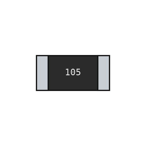 贴片电阻2 1M
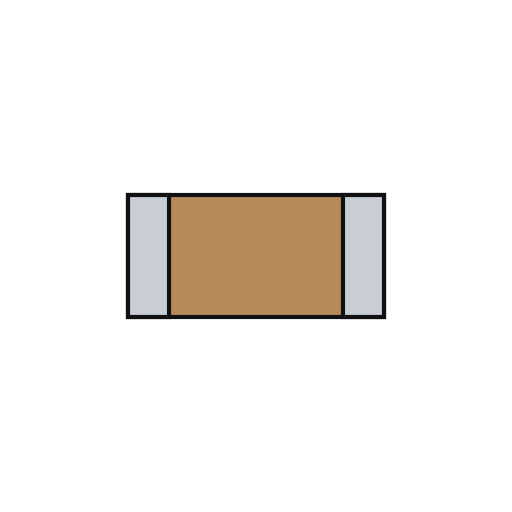 贴片陶瓷电容11 7x100n, 2x1u, 2x22p
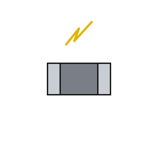 贴片压敏电阻2 Z1, Z2
 磁珠1 L1
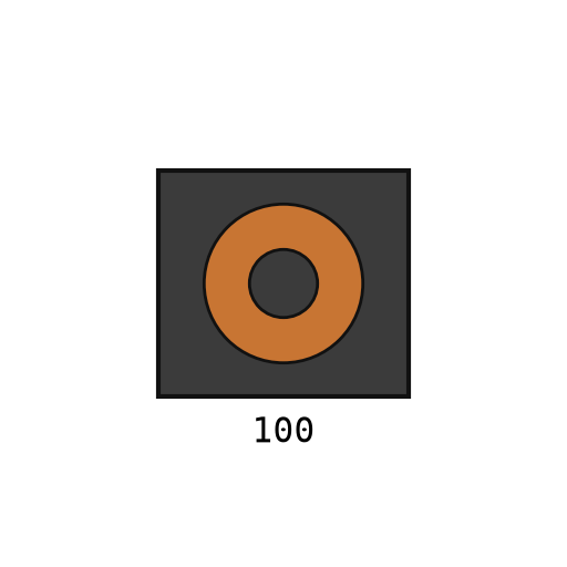 贴片电感1 L2
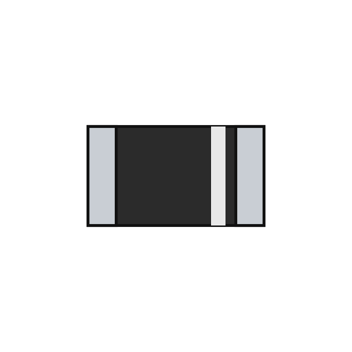 贴片二极管2 D2, D3
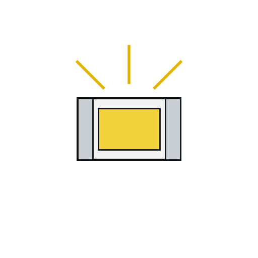 贴片 LED4 1 green, 3 yellow
 焊锡丝1 a little
所需工具:
 助焊剂
 尖头镊子
 热风返修台
 电烙铁放大目镜
3
3
Fit the power and chip parts
Fit the power and chip parts
Solder the ATmega16U2 (U3), the 16 MHz resonator Y2 and crystal Y1, the 5 V regulator NCP1117 (U1) and 3.3 V regulator LP2985 (U2), the LMV358 op-amp (U5), the FDN340P transistor (T1), the M7 diode (D1), the 500 mA resettable fuse (F1) and the 47 uF capacitors PC1, PC2 with their polarity as marked.
此步骤所需材料:
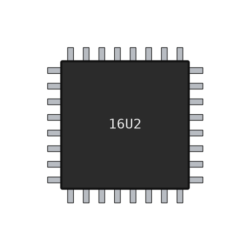 ATmega16U2 微控制器1 U3
 压电陶瓷谐振器1 Y2
 石英晶体1 Y1
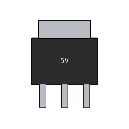 线性稳压器2 U1 5 V, U2 3.3 V
 运算放大器集成电路1 U5 LMV358
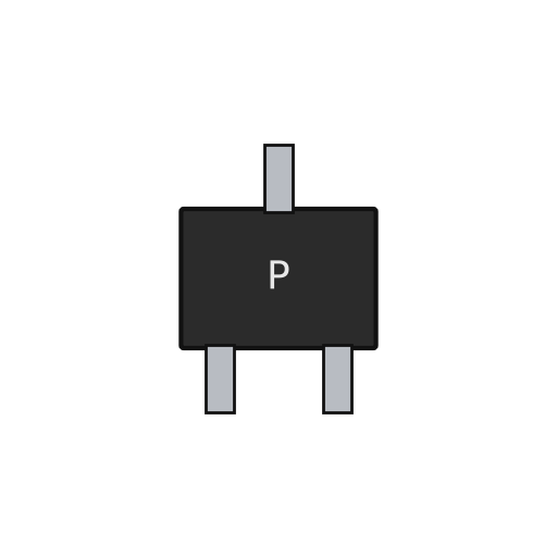 P 沟道 MOSFET1 T1贴片二极管1 D1 M7
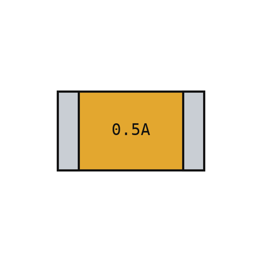 自恢复保险丝1 F1
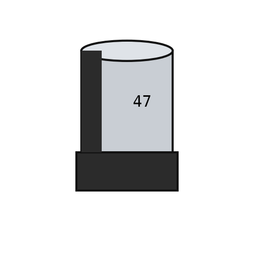 有极性贴片电容2 PC1, PC2焊锡丝1 a little
所需工具:
助焊剂尖头镊子热风返修台电烙铁放大目镜4
4
Fit the through-hole parts
Fit the through-hole parts
Solder the USB-B socket (X2), the DC jack (X1), the reset switch, the female headers (one 10-way, two 8-way, one 6-way) and the two 2x3 ICSP headers. Seat the ATmega328P in its place (ZU4).
此步骤所需材料:
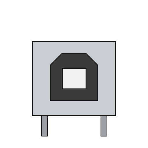 USB-B 插座1 X2
 桶形电源插座1 X1
 按钮1 RESET
 排针6 10x1, 2x 8x1, 6x1 female; 2x 3x2 ICSP
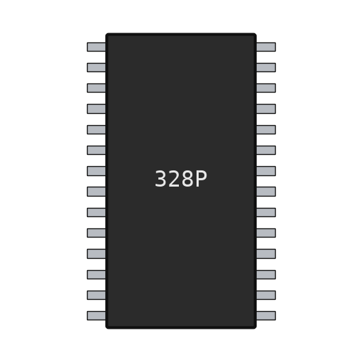 ATmega328P 微控制器1 ZU4焊锡丝1 as needed
所需工具:
电烙铁5
5
Flash and check
Flash and check
Check with a meter that 5 V and GND are not shorted. Through the ICSP headers, load the USB-to-serial firmware into the ATmega16U2 and the bootloader into the ATmega328P. Plug in USB: the green ON LED lights, and the blink test in the next step flashes the L LED. Ours: an AVR ISP programmer and a multimeter.
此步骤所需材料:
 Arduino Uno 固件1 download
所需工具:
 万用表
 AVR ISP 编程器
 USB-B 线
6
6
The blink test
The blink test
blink_test.ino: the same check as Arduino's Blink example. Upload it over USB from the Arduino IDE with the board set to Arduino Uno; the L LED on pin 13 turns on for one second and off for one second, over and over. If it does, both processors, the USB link and the bootloader work.
blink_test.inocpp
所需工具:
USB-B 线材料
24- 1 UNO-TH Rev3e layout占位符
- 4 RN1-RN4占位符
- 2 1M占位符
- 11 7x100n, 2x1u, 2x22p占位符
- 2 Z1, Z2占位符
- 1 L1占位符
- 1 L2占位符
- 1 D1 M7占位符
- 4 1 green, 3 yellow占位符
- 1 as needed占位符
- 1 U3占位符
- 1 Y2占位符
- 1 Y1占位符
- 2 U1 5 V, U2 3.3 V占位符
- 1 U5 LMV358占位符
- 1 T1占位符
- 1 F1占位符
- 2 PC1, PC2占位符
- 1 X2占位符
- 占位符
- 占位符
- 占位符
- 1 ZU4占位符
- 1 download占位符
相关蓝图
这些蓝图共享知识——技术、材料或原理
CC0 公共领域
此蓝图以 CC0 协议发布。你可以自由复制、修改、分发和使用此作品,无需征得许可。
通过购买蓝图中的产品支持创客,他们将获得 创客佣金 (由供应商设定),或创建此蓝图的新版本并将其作为连接包含在你自己的蓝图中以分享收入。