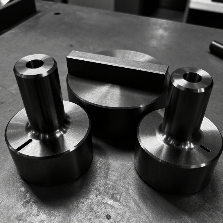


Oldham Coupling
说明
Turn the two hubs
Turn the two hubs
Two identical discs, each with a slot across one face.
- Cut two 90 mm discs from 18 mm Baltic birch plywood.
- Bore each centre 8.0 mm for its shaft.
- On one face of each, mark a slot 20 mm wide across the full diameter, passing through the centre.
- Cut each slot 8 mm deep — a router or repeated saw kerfs cleaned with a chisel and file.
- Check both slots are the same width along their whole length.
Modern build spec (derived). Ply hubs and a 20 mm slot make this an afternoon's work with hand tools. Oldham's own were cast iron with machined slots, and commercial couplings today use two aluminium hubs with an acetal centre disc — the acetal being both the bearing surface and the deliberate weak point.
Slot width consistency matters more than exact width. The tongue is fitted to the slot, so 20.4 mm is fine as long as it is 20.4 mm everywhere.此步骤所需材料:
 波罗的海桦木胶合板1 张
所需工具:
 钢丝锯(曲线锯)
 充电式电钻
充电式电钻 钻头套装
钻头套装 锉刀套装
锉刀套装 组合角尺
组合角尺 6 英寸数显卡尺
Make the floating disc — tongues at 90 degrees
Make the floating disc — tongues at 90 degrees
The single part that does all the work.
- Cut an 85 mm disc from 6 mm clear acrylic sheet.
- Cut two tongues 20 mm wide from the same acrylic, each 80 mm long.
- Fix one tongue across each face — crucially, the two tongues must be at 90 degrees to one another.
- Fasten each with M4 × 16 socket head cap screws × 2, M4 flat washers × 4 and M4 hex nuts × 2, countersunk so nothing protrudes.
- File each tongue to a sliding fit in its slot — free to slide, no perceptible rock.
Clear acrylic is chosen deliberately: you can watch the disc's centre orbit while the coupling turns, which is the whole behaviour and is invisible in a metal one.
Ninety degrees is not approximate. If the tongues are at 80 degrees the coupling binds and loads the shafts exactly as the rigid coupling it was meant to replace.此步骤所需材料:
 亚克力板1 张
 内六角圆柱头螺钉4 个
 平垫圈8 个
 六角螺母4 个
所需工具:
钢丝锯(曲线锯)充电式电钻 锪孔钻头套装锉刀套装
 内六角扳手组组合角尺
Mount two shafts DELIBERATELY out of line
Mount two shafts DELIBERATELY out of line
The point is offset, so build the offset in and make it adjustable.
- Cut a baseplate 300 × 180 mm from 18 mm ply.
- Make two pillow blocks, each holding a 608 bearing, and fit a shaft of 25 mm aluminium round bar in each.
- Mount the first block on the centreline with M5 × 40 socket head cap screws × 2, M5 flat washers × 4, M5 hex nuts × 2.
- Give the SECOND block vertical slots instead of holes, so it can be set anywhere from 0 to 12 mm off the centreline.
- Fit a hub to each shaft, drop the floating disc between them, and set the offset to zero.
此步骤所需材料:
波罗的海桦木胶合板1 张 铝圆棒1 个
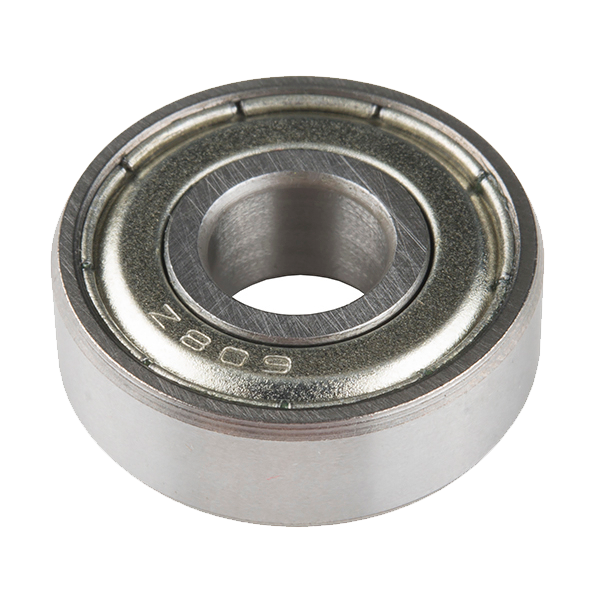 Ball Bearing - Non-Flanged (8mm Bore, 22mm OD)2 个平垫圈8 个六角螺母4 个
所需工具:
充电式电钻钻头套装 曲线锯内六角扳手组6 英寸数显卡尺
Prove constant velocity, then find the limit
Prove constant velocity, then find the limit
Two measurements: the promise, then the boundary.
- Fit protractor discs to both shafts and align at zero.
- At zero offset, turn the input in 30 degree steps and record the output. They match exactly.
- Now set 8 mm offset and repeat the whole revolution.
- They still match exactly — unlike the universal joint, which was already several degrees out at angle.
- Increase the offset until the disc's tongue reaches the end of a slot. Record that figure.
此步骤所需材料:
波罗的海桦木胶合板1 包所需工具:
6 英寸数显卡尺组合角尺History and where it belongs
History and where it belongs
John Oldham (1779-1840), an Irish engineer, patented the coupling in 1821. He was chief engineer to the Bank of Ireland and later the Bank of England, and the coupling came out of machinery for printing banknotes — a job needing exact registration between rollers that could not be perfectly aligned. He also invented a paddle wheel and worked on note-numbering machines.
Its two genuine advantages: exact constant velocity regardless of offset, and a floating disc that is a deliberate sacrificial element — overload it and the cheap centre shears rather than the shafts or bearings. Commercial couplings still exploit this, using an acetal disc between aluminium hubs so the failure is predictable and cheap.
Its honest limits: the disc orbits at twice shaft speed, so it is an unbalanced mass that rules the coupling out at high speed. It tolerates almost no ANGULAR misalignment. And the sliding faces wear, needing lubrication or a self-lubricating plastic.
Set against its siblings: the universal joint takes angle and torque but varies its output velocity; the Oldham takes parallel offset at exactly constant velocity but no angle; a flexible or jaw coupling takes a little of both while absorbing shock, at the cost of torsional stiffness. Three different definitions of "misaligned", three different mechanisms, no overall winner — which is why all three are still manufactured today.
材料
10- 1 张占位符
- 1 张占位符
- 4 个占位符
- 8 个占位符
- 4 个占位符
- 1 个占位符
- $1.27
- 8 个占位符
- 4 个占位符
- 1 包占位符
所需工具
9- 占位符
- 1 vendor sell this, none ship to you yet占位符
- 占位符
- 占位符
- 占位符
- 占位符
- 占位符
- 占位符
- 1 vendor sell this, none ship to you yet占位符
CC0 公共领域
此蓝图以 CC0 协议发布。你可以自由复制、修改、分发和使用此作品,无需征得许可。
通过购买蓝图中的产品支持创客,他们将获得 创客佣金 (由供应商设定),或创建此蓝图的新版本并将其作为连接包含在你自己的蓝图中以分享收入。