艺术
美容与健康
工艺
文化与历史
娱乐
环境
食品与饮料
逆向工程
科学
体育
技术
可穿戴设备


The Chip-on-Board Breakout: From a 0.4 mm Mezzanine to Pins You Can Reach
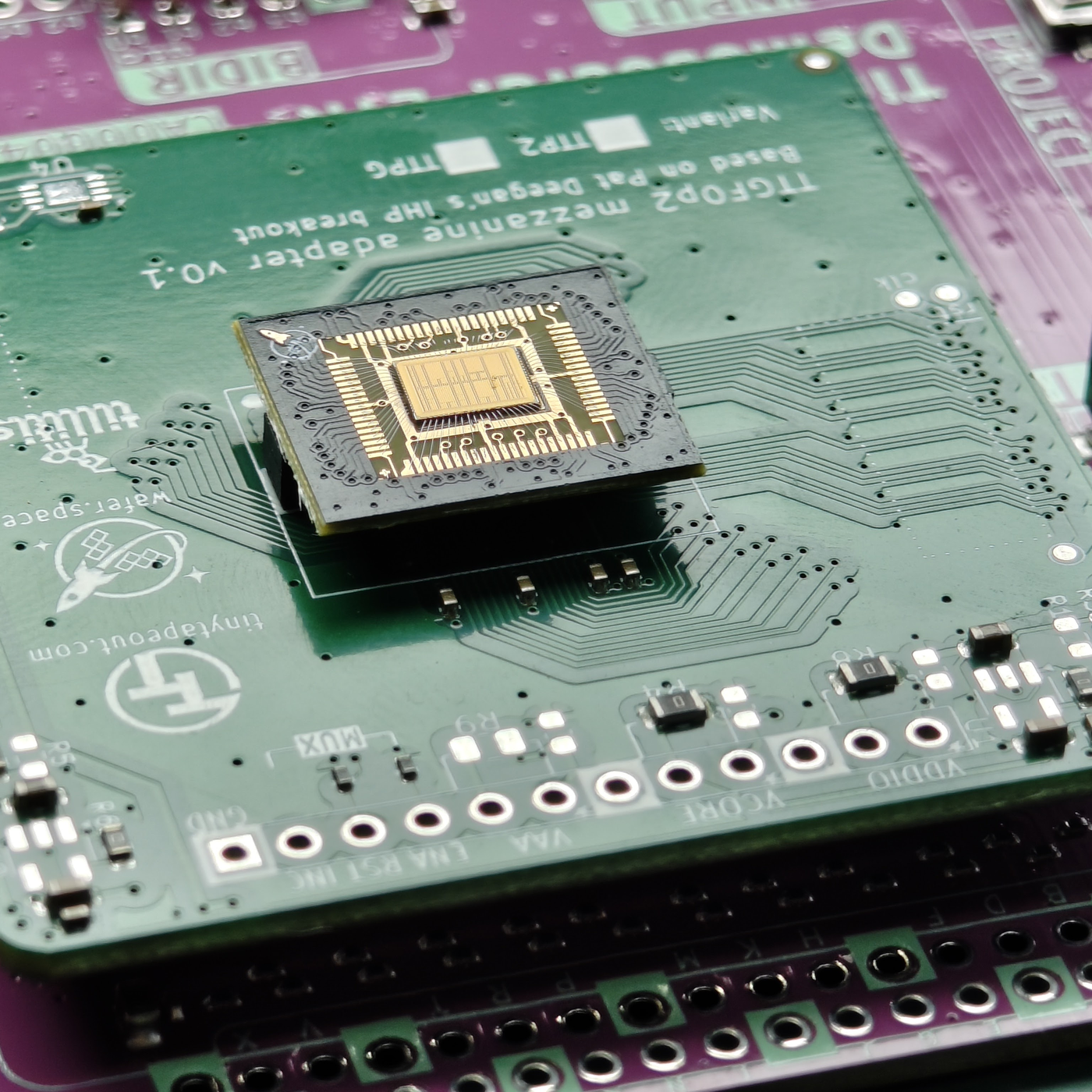
A chip from a shared wafer comes back tiny. On wafer.space's Run 1 it arrived as a chip-on-board part 14 × 16 mm, with the die wire-bonded under epoxy and a 70-pin mezzanine connector underneath at 0.4 mm pitch. Nothing on a bench can touch pins that small, so the first thing to build is a board that carries them back out.
wafer.space publishes example breakout motherboards in KiCad under Apache-2.0: one sheet, two boards. Each has the mating 70-pin mezzanine socket; one breaks the pins out to two 1 × 35 rows of 0.1-inch pin headers, the other to two rows of 35 castellated edge pads at 1 mm.
This rung works out why the fine pitch is needed and what spreading it out costs in board length, shows the published schematic, and builds the header version.
高级
About a day of soldering, plus board fabrication
说明
1
1
Pitch against board edge
Pitch against board edge
正在加载 Jupyter 笔记本…
2
2
Where the chip comes from
Where the chip comes from
The embedded blueprint designs the chip and orders it. This rung builds the board it plugs into.
3
3
What the chip-on-board plugs into
What the chip-on-board plugs into
From wafer.space's Run 1 documentation: the full-slot chip-on-board is 14 × 16 mm; the die's 74 bond pads follow the Tiny Tapeout convention, and all grounds are tied together on the default breakout. It carries a 70-pin, 0.4 mm pitch mezzanine connector (LCSC C19089236; the mating part is LCSC C19089262).
So that every project fits the same boards, the default breakouts share the same wire-bonding layout, the same 14 × 16 mm footprint and the same connector position; traces, signal types and net assignments are left to the designer. wafer.space notes that pinouts, connectors and footprints are specific to each run.
4
4
The published breakout schematic
The published breakout schematic
wafer.space's example motherboards, from the chip-on-board-wire-bonded-pcbs repository (run-1/motherboards, Apache-2.0), shown as published. On the left, the ".1\" Header" board: the mezzanine socket J102 (HCTL HC-PBB40C-70DP-0.4V-02, 70 pins at 0.4 mm) broken out to the 1 × 35 pin headers J101 and J103 at 2.54 mm. On the right, the "Castellated" board: the same socket J105 broken out to the 1 × 35 castellated edges J104 and J106 at 1 mm, so the whole breakout can itself be soldered onto a larger board.
加载 KiCanvas 查看器...
专业 PCB 设计查看器
5
5
Build the header board
Build the header board
Download the run-1/motherboards project from the repository and open it in KiCad. The files are saved by KiCad 10, so an older KiCad will not open them. Plot the Gerber and drill files and order the board from a PCB fabricator, with a solder-paste stencil for the mezzanine footprint.
Hold the stencil over the mezzanine pads and spread lead-free solder paste across it in one stroke. Place the socket with fine tweezers, square to its pads, and reflow it with the hot-air station until the paste flows and settles. Inspect every one of the 70 joints with the loupe; clear any bridge between neighbouring pins with flux and the iron or hot air.
Solder the two 1 × 35 pin headers with the iron. Before you plug in a chip, check with the multimeter that no two neighbouring header pins are shorted, and that each header pin reaches the socket pin the schematic connects it to.
此步骤所需材料:
 印制电路板1 个
 板对板连接器1 个
 排针2 个
排针2 个 锡膏(无铅)1 个
 锡铅焊料1 个
 熔剂1 个
熔剂1 个所需工具:
 热风返修台
热风返修台 电烙铁
电烙铁 尖头镊子
尖头镊子 放大目镜
放大目镜 万用表
万用表 台式电脑
台式电脑6
6
A breakout that shorts or does not connect
A breakout that shorts or does not connect
Breakout board troubleshooting.
Flow
Loading...
7
7
Sources and honest limits
Sources and honest limits
**Sources**, read 29 September 2026: wafer.space's chip-on-board-wire-bonded-pcbs repository (README, run-1/README and run-1/motherboards, Apache-2.0). The schematic in step 4 is theirs, unchanged. The photograph is theirs too, from the same repository: a Run 1 chip-on-board seated on a Tiny Tapeout mezzanine adapter board (TTGF02, v0.1), not the header board built in step 5.
**Honest limits.** This rung has not been built for this blueprint; the soldering steps are standard practice for a 0.4 mm surface-mount connector, not wafer.space instructions. The pinout and footprint are Run 1's, and wafer.space says they are expected to change in later runs, so check the current run's documentation before ordering boards.
材料
6- 1 个占位符
- 1 个占位符
- 1 个占位符
- 1 个占位符
- 1 个占位符
相关蓝图
这些蓝图共享知识——技术、材料或原理


CC0 公共领域
此蓝图以 CC0 协议发布。你可以自由复制、修改、分发和使用此作品,无需征得许可。
通过购买蓝图中的产品支持创客,他们将获得 创客佣金 (由供应商设定),或创建此蓝图的新版本并将其作为连接包含在你自己的蓝图中以分享收入。