
Zusammenarbeit
KUNST
SCHÖNHEIT & WELLNESS
HANDWERK
KULTUR & GESCHICHTE
UNTERHALTUNG
UMFELD
ESSEN & GETRÄNKE
REVERSE ENGINEERING
WISSENSCHAFTEN
SPORT
TECHNOLOGIE
WEARABLES
Adjustable Bench Power Supply: Constant Voltage / Constant Current with Cross-Over Lamps (Gately, Forbro, US 3,303,411, 1967)
Ed

Erstellt von

Ed

3. November 2026FI
3
0
0
0
0

Adjustable Bench Power Supply: Constant Voltage / Constant Current with Cross-Over Lamps (Gately, Forbro, US 3,303,411, 1967)

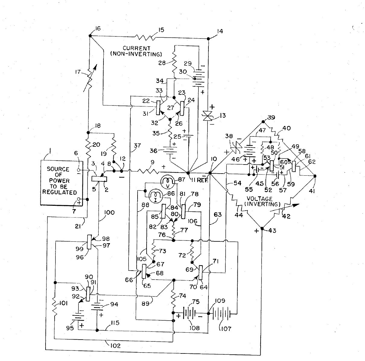
An all-transistor bench supply with two knobs: one sets the voltage, the other the current. It holds the set voltage until the load tries to draw more than the set current, then switches at once to holding the current, and back again, with no in-between state. Two lamps show which mode is in control. Result: an adjustable constant-voltage / constant-current DC supply with mode lamps. Source: J. R. Gately (Forbro Design), US 3,303,411 (1967). Unknown: all component values and ratings. Builds on the same inventor's 1966 current-limited supply. Picture: the patent drawing.
Erfahren
Unknown

Anweisungen

1

Build the raw supplies

In a case, wire the cord through a switch and fuse to two power transformers, each with rectifiers and a filter: one gives the main power to be regulated, the other the bias supplies, held steady by Zener diodes. Not given: the voltages. Ours: the case, switch and fuse.

Materialien für diesen Schritt:

AluminiumgehäuseAluminiumgehäuse1 Stück
Anschlussleitung mit SteckerAnschlussleitung mit Stecker1 Stück
KippschalterKippschalter1 Stück
SchmelzsicherungSchmelzsicherung1 Stück
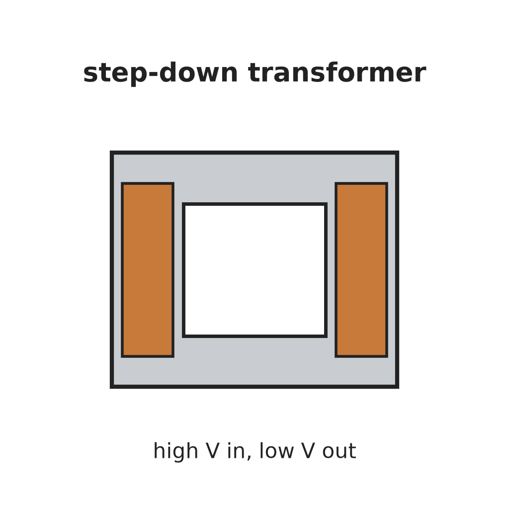
AbwärtstransformatorAbwärtstransformator2 Stück
DiodeDiode6 rectifiers
ElektrolytkondensatorElektrolytkondensator3 filters
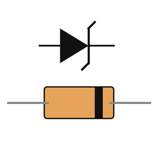
Z-DiodeZ-Diode2 bias

Benötigte Werkzeuge:

HandbohrerHandbohrer
Schraubendreher-SatzSchraubendreher-Satz
2

Fit the pass transistor and current bridge

Put a power transistor on a heat sink in series with the output: collector to the negative supply, emitter through a current-sensing resistor to the negative output terminal. Make the current bridge from the sensing resistor, a reference Zener, a reference resistor and the adjustable current-control resistor: the output current is proportional to its setting. A small trimming resistor sets the maximum current. Not given: the values.

Materialien für diesen Schritt:

LeistungstransistorLeistungstransistor1 series pass
KühlkörperKühlkörper1 Stück
Z-DiodeZ-Diode1 current reference
RegelwiderstandRegelwiderstand1 current control
WiderstandWiderstand1 sensing, reference, trim set
PolklemmePolklemme2 output + and -

Benötigte Werkzeuge:

LötkolbenLötkolben
3

Build the voltage bridge

Make the voltage bridge from a reference Zener, a reference resistor, the adjustable voltage-control resistor and the load itself across the output. A small trimming resistor sets the maximum voltage. Add two resistors that feed the current bridge enough extra to cover the voltage bridge's own current and any voltmeter across the output, so low currents are still held exactly.

Materialien für diesen Schritt:

Z-DiodeZ-Diode1 voltage reference
RegelwiderstandRegelwiderstand1 voltage control
WiderstandWiderstand1 reference, trim, compensation set

Benötigte Werkzeuge:

LötkolbenLötkolben
4

Build the amplifiers and cross-over

Give each bridge an error amplifier. Feed the two amplified errors to the bases of a pair of transistors sharing one emitter resistor: whichever base is the more negative takes control and cuts the other off, so the supply is always cleanly in voltage mode or current mode. Amplify the shared emitter signal through two more transistors to drive the pass transistor's base. Add an emitter-follower clamp on the bias line. Not given: the transistor types.

Materialien für diesen Schritt:

LeiterplatteLeiterplatte1 Stück
TransistorsortimentTransistorsortiment1 error amplifiers, cross-over pair, drivers, clamp
WiderstandWiderstand1 Set
PotentiometerPotentiometer1 clamp divider
LötdrahtLötdraht1 as needed

Benötigte Werkzeuge:

LötkolbenLötkolben
5

Fit the mode lamps and use it

From the cross-over pair, drive two lamp transistors, each lighting one lamp: one for voltage mode, one for current mode. In use, set the voltage and the current limit. With a light load the voltage lamp is lit and the voltage holds; if the load tries to draw more than the set current, the supply switches to holding the current and the current lamp lights.

Materialien für diesen Schritt:

TransistorsortimentTransistorsortiment1 two lamp drivers
LampenfassungLampenfassung2 Stück
GlühbirneGlühbirne2 Stück

Benötigte Werkzeuge:

Schraubendreher-SatzSchraubendreher-Satz

Materialien

19

Benötigte Werkzeuge

3

CC0 Gemeinfrei

Dieser Blueprint ist unter CC0 veröffentlicht. Sie dürfen dieses Werk für jeden Zweck frei kopieren, ändern, verbreiten und verwenden, ohne um Erlaubnis zu fragen.

Unterstützen Sie den Maker, indem Sie Produkte über seinen Blueprint kaufen, wo er eine Maker-Provision von Anbietern festgelegt, verdient. Oder erstellen Sie eine neue Iteration dieses Blueprints und verbinden Sie ihn in Ihrem eigenen Blueprint, um Einnahmen zu teilen.

Diskussion

(0)

Anmelden um an der Diskussion teilzunehmen

Kommentare werden geladen...