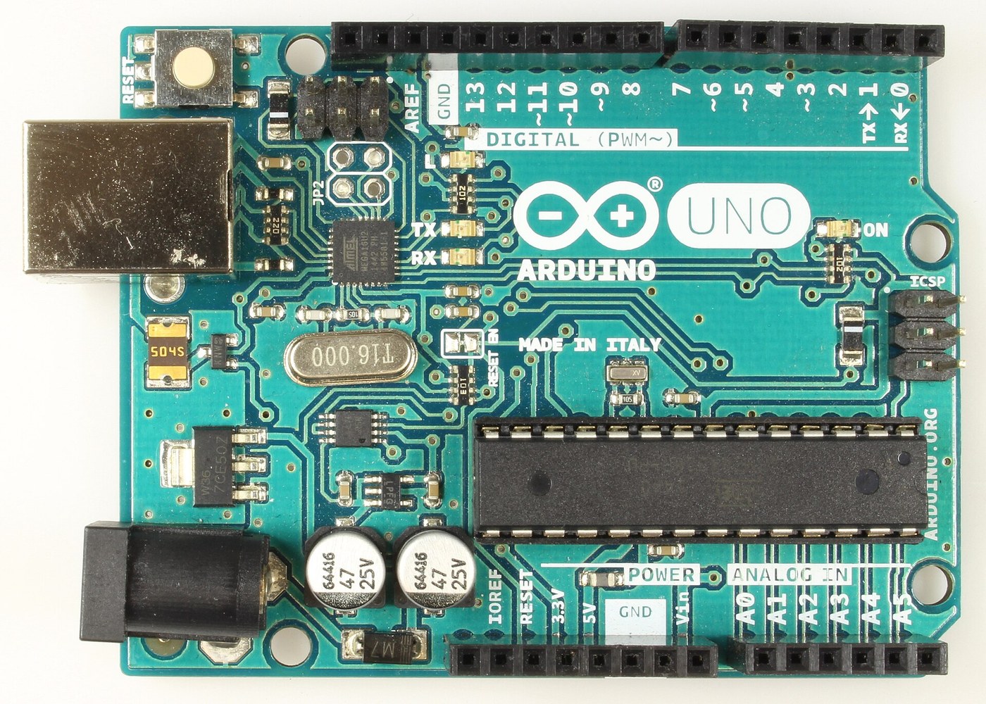


Arduino Uno R3: Assembled from Arduino's Open UNO-TH Rev3e Design Files and Flashed over ICSP
Anweisungen
Get the bare board
Get the bare board
Materialien für diesen Schritt:
 Leiterplatte1 UNO-TH Rev3e layout
Benötigte Werkzeuge:
 Einschlaglupe
Fit the small surface-mount parts
Fit the small surface-mount parts
Materialien für diesen Schritt:
 Chip-Widerstandsnetzwerk4 RN1-RN4
 Chip-Widerstand2 1M
 Keramik-Chipkondensator11 7x100n, 2x1u, 2x22p
 Chip-Varistor2 Z1, Z2
 Ferritperle1 L1
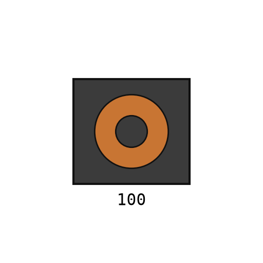 SMD-Induktivität1 L2
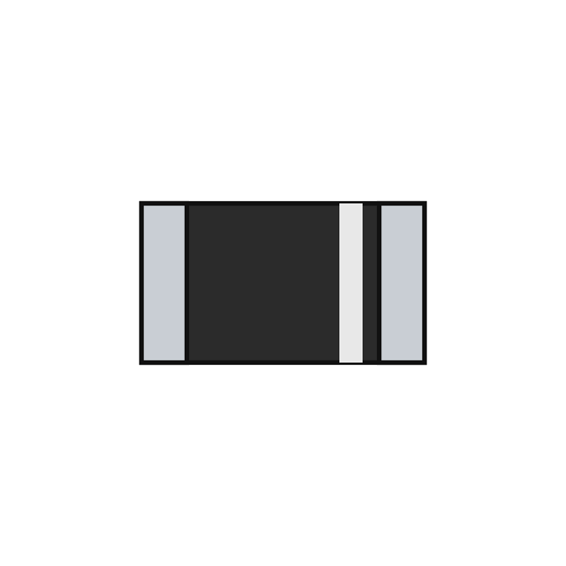 SMD-Diode2 D2, D3
 Chip-LED4 1 green, 3 yellow
 Lötdraht1 a little
Benötigte Werkzeuge:
 Flussmittel
 Spitzpinzette
 Heißluft-Reworkstation
 LötkolbenEinschlaglupe
Fit the power and chip parts
Fit the power and chip parts
Materialien für diesen Schritt:
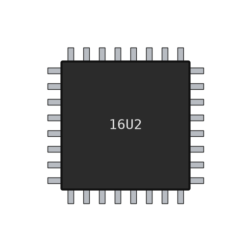 ATmega16U2-Mikrocontroller1 U3
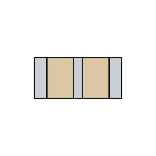 Piezokeramischer Resonator1 Y2
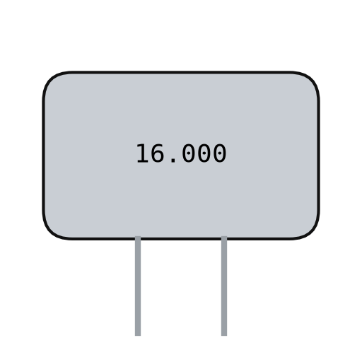 Schwingquarz1 Y1
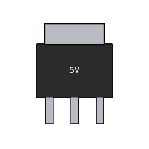 Linearer Spannungsregler2 U1 5 V, U2 3.3 V
 Operationsverstärker-IC1 U5 LMV358
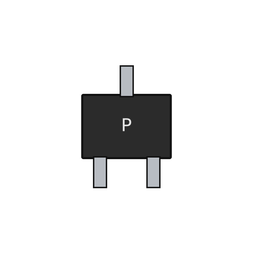 P-Kanal-MOSFET1 T1SMD-Diode1 D1 M7
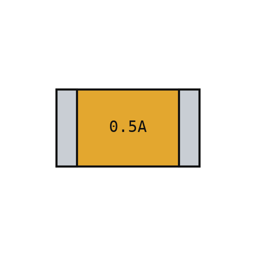 Rückstellende Sicherung1 F1
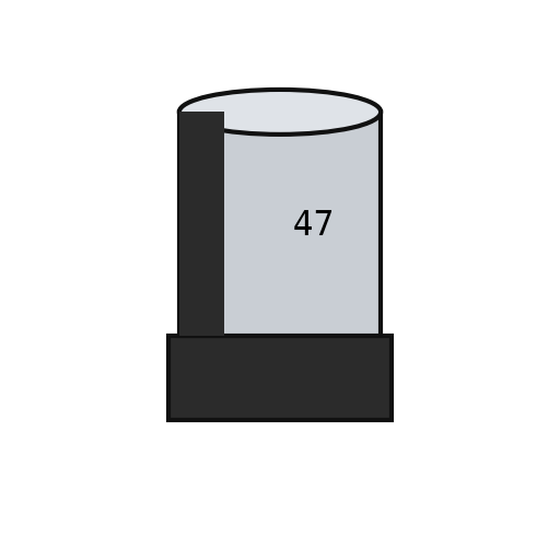 Gepolter Chipkondensator2 PC1, PC2Lötdraht1 a little
Benötigte Werkzeuge:
FlussmittelSpitzpinzetteHeißluft-ReworkstationLötkolbenEinschlaglupeFit the through-hole parts
Fit the through-hole parts
Materialien für diesen Schritt:
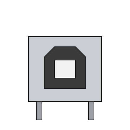 USB-B-Buchse1 X2
 Hohlsteckerbuchse1 X1
 Drucktaster1 RESET
 Stiftleiste6 10x1, 2x 8x1, 6x1 female; 2x 3x2 ICSP
 ATmega328P-Mikrocontroller1 ZU4Lötdraht1 as needed
Benötigte Werkzeuge:
LötkolbenFlash and check
Flash and check
Materialien für diesen Schritt:
 Arduino-Uno-Firmware1 download
Benötigte Werkzeuge:
 Multimeter
 AVR-ISP-Programmiergerät
 USB-B-Kabel
The blink test
The blink test
Benötigte Werkzeuge:
USB-B-KabelMaterialien
24- 1 UNO-TH Rev3e layoutPlatzhalter
- 4 RN1-RN4Platzhalter
- 2 1MPlatzhalter
- 11 7x100n, 2x1u, 2x22pPlatzhalter
- 2 Z1, Z2Platzhalter
- 1 L1Platzhalter
- 1 L2Platzhalter
- 1 D1 M7Platzhalter
- 4 1 green, 3 yellowPlatzhalter
- 1 as neededPlatzhalter
- Platzhalter
- Platzhalter
- 1 Y1Platzhalter
- 2 U1 5 V, U2 3.3 VPlatzhalter
- 1 U5 LMV358Platzhalter
- 1 T1Platzhalter
- Platzhalter
- 2 PC1, PC2Platzhalter
- 1 X2Platzhalter
- Platzhalter
- Platzhalter
- Platzhalter
- Platzhalter
- 1 downloadPlatzhalter
Benötigte Werkzeuge
8- Platzhalter
- Platzhalter
- Platzhalter
- Platzhalter
- 2 vendors sell this, none ship to you yetPlatzhalter
- Platzhalter
- Platzhalter
- 1 vendor sell this, none ship to you yetPlatzhalter
Dieser Bauplan stellt her
Verwandte Blueprints
Diese Blueprints teilen Wissen — Techniken, Materialien oder Prinzipien
CC0 Gemeinfrei
Dieser Blueprint ist unter CC0 veröffentlicht. Sie dürfen dieses Werk für jeden Zweck frei kopieren, ändern, verbreiten und verwenden, ohne um Erlaubnis zu fragen.
Unterstützen Sie den Maker, indem Sie Produkte über seinen Blueprint kaufen, wo er eine Maker-Provision von Anbietern festgelegt, verdient. Oder erstellen Sie eine neue Iteration dieses Blueprints und verbinden Sie ihn in Ihrem eigenen Blueprint, um Einnahmen zu teilen.