KUNST
SCHÖNHEIT & WELLNESS
HANDWERK
KULTUR & GESCHICHTE
UNTERHALTUNG
UMFELD
ESSEN & GETRÄNKE
REVERSE ENGINEERING
WISSENSCHAFTEN
SPORT
TECHNOLOGIE
WEARABLES
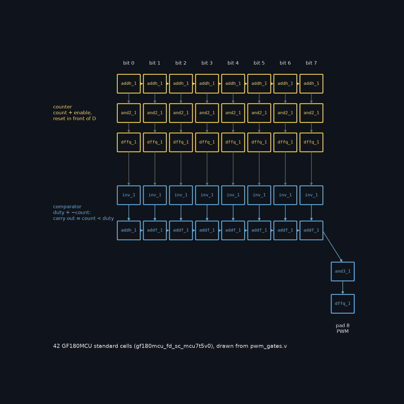
Youblob (drawn from the netlist) · CC0


Your chip_core as Standard Cells: 42 GF180MCU Gates, Proven Equal to the Verilog
A foundry does not make Verilog. It makes transistors, arranged as standard cells: small, fixed layouts such as an inverter, an AND gate, a full adder or a flip-flop, each drawn once by the library's authors and placed thousands of times. Between your Verilog and the wafer, a synthesis tool rewrites every line of your design as a list of those cells, a netlist.
This rung does that by hand for the previous rung's PWM dimmer, with the cells of the GF180MCU library that wafer.space's template uses by default. The dimmer becomes 42 cells: a counter of half adders and flip-flops, and a comparator that is really a subtractor. Then the netlist is simulated on the PDK's own Verilog models of those cells, the same models the template's gate-level simulation uses, and compared with the original Verilog on every clock.
Everything here was run for this blueprint with Icarus Verilog 12.0 and cocotb 2.1.0: the gates and the Verilog agreed on all 96,800 clocks compared, and a deliberately broken netlist was caught at once.
Erfahren
An evening
Anweisungen
1
1
The comparator is a subtractor
The comparator is a subtractor
Jupyter-Notebook wird geladen …
2
2
The Verilog this rung turns into gates
The Verilog this rung turns into gates
The embedded blueprint writes the dimmer in Verilog and tests it. This rung rewrites the same logic as cells.
3
3
What a standard cell is
What a standard cell is
The template's default library is gf180mcu_fd_sc_mcu7t5v0: GlobalFoundries' 180 nm cells, 7 tracks high, for 5 V. Every cell sits on the library's placement site, 0.56 by 3.92 micrometres, and comes as a set of views: a layout for the foundry, a timing file for the tools, and a Verilog model for simulation.
Six cells are enough for the dimmer. addh_1 is a half adder (S = A xor B, CO = A and B); addf_1 a full adder; and2_1 and and3_1 AND gates; inv_1 an inverter; dffq_1 a D flip-flop that copies D to Q on each rising clock edge. That flip-flop has no reset pin, so the reset goes in front of it: an AND gate lets the next count through only while rst_n is high, which clears the counter on the first clock edge in reset. That is a synchronous reset, exactly what the Verilog asked for.
In the real flow, LibreLane runs the synthesis, choosing cells and sizes itself; its netlist also carries cells added for the layout, such as buffers. Writing 42 of them by hand once shows what the tool is doing.
4
4
The netlist
The netlist
pwm_gates.v: the dimmer's logic as 42 GF180MCU cells. Each line is one cell and the names of its pins are the library's. The two generate loops write the eight identical bit slices; the comparator's bit 0 is a half adder because nothing carries into it. The MUTANT block is the deliberate mistake used in step 7. chip_core_gates.sv is the previous rung's chip_core with its two always_ff blocks replaced by this module.
pwm_gates.vverilog
Benötigte Werkzeuge:
 Desktop-Computer
5
5
Both versions side by side
Both versions side by side
tb_equiv.sv puts the Verilog core and the gate core next to each other on the same inputs, so a test can compare their outputs directly. Nothing in it is logic: it is only wiring.
tb_equiv.svsystemverilog
Benötigte Werkzeuge:
Desktop-Computer6
6
The test that proves them equal
The test that proves them equal
test_equiv.py builds the design against the PDK's own cell models, primitives.v and gf180mcu_fd_sc_mcu7t5v0.v from the gf180mcuD build the template pins, with FUNCTIONAL defined: the cells' logic without their timing checks, as the template's gate-level simulation does. Three tests: the flip-flops start unknown and one clock in reset clears them; every duty value from 0 to 255 for 300 clocks each; and 20,000 clocks of random duty changes, enable toggles and resets. Download the PDK with the template's make clone-pdk, or unpack the gf180mcu_fd_sc_mcu7t5v0 archive from the ciel releases, and point PDK_ROOT at it.
test_equiv.pypython
Benötigte Werkzeuge:
Desktop-Computer7
7
What the simulation printed
What the simulation printed
Run for this blueprint with Icarus Verilog 12.0 and cocotb 2.1.0:
test_equiv.test_reset_clears_x PASS
test_equiv.test_every_duty_lockstep PASS (76800 clocks compared, 0 differences)
test_equiv.test_random_lockstep PASS (20000 random clocks compared, 0 differences)
TESTS=3 PASS=3 FAIL=0 SKIP=0
To prove the test can fail, the netlist was built with MUTANT defined, which feeds count[0] into the comparator's first adder instead of its inverse: one missing inverter. Both comparison tests failed at once, the first at duty 1, where the gates held the output low and the Verilog drove it high.
The first test shows something a Verilog simulation hides. In the gate model, a flip-flop has no value until a clock edge gives it one, so every output is X, unknown, until reset has been clocked in. A real chip powers up the same way, with each flip-flop in whichever state it happens to fall into. That is why the reset must reach every flip-flop that matters.
8
8
The same check in the template
The same check in the template
In the template, the flow does the synthesis. make librelane runs it and saves the results to final/; make sim-gl then runs the template's cocotb testbench on final/pnl/chip_top.pnl.v, the netlist after placement and routing, with the same library models and the FUNCTIONAL and USE_POWER_PINS defines. Its test has to be rewritten for your design first, as the previous rung describes.
Neither gate-level simulation checks timing: FUNCTIONAL leaves the delays out. Timing is checked by the flow's static timing analysis against the clock in the template's configuration, a 40 ns period (25 MHz). The comparator here is a carry chain eight adders long, and a chain like that is what such an analysis looks at first.
9
9
A gate-level simulation that will not build or will not match
A gate-level simulation that will not build or will not match
Gate-level simulation troubleshooting.
Flow
Loading...
10
10
Sources and honest limits
Sources and honest limits
**Sources**, read 29 September 2026: the GF180MCU PDK at the commit the template pins (gf180mcuD, f6eeac7dad085ffcc829ccfd721f7b4ce39edcf7, from the fossi-foundation ciel releases; Apache-2.0): the cell models gf180mcu_fd_sc_mcu7t5v0.v and primitives.v, the timing file gf180mcu_fd_sc_mcu7t5v0__tt_025C_5v00.lib for the areas, and the technology LEF for the site size. The wafer-space/gf180mcu-project-template repository (Makefile, cocotb/chip_top_tb.py, librelane/config.yaml, librelane/slots/slot_0p5x0p5.yaml; Apache-2.0).
**Honest limits.** The netlist is written by hand, not produced by synthesis; a synthesis tool would choose its own cells and sizes. The simulation uses the cells' functional models only, with no delays, so it proves the logic, not the timing. Nothing here has been placed, routed or made.
Verwandte Blueprints
Diese Blueprints teilen Wissen — Techniken, Materialien oder Prinzipien




CC0 Gemeinfrei
Dieser Blueprint ist unter CC0 veröffentlicht. Sie dürfen dieses Werk für jeden Zweck frei kopieren, ändern, verbreiten und verwenden, ohne um Erlaubnis zu fragen.
Unterstützen Sie den Maker, indem Sie Produkte über seinen Blueprint kaufen, wo er eine Maker-Provision von Anbietern festgelegt, verdient. Oder erstellen Sie eine neue Iteration dieses Blueprints und verbinden Sie ihn in Ihrem eigenen Blueprint, um Einnahmen zu teilen.