KUNST
SCHÖNHEIT & WELLNESS
HANDWERK
KULTUR & GESCHICHTE
UNTERHALTUNG
UMFELD
ESSEN & GETRÄNKE
REVERSE ENGINEERING
WISSENSCHAFTEN
SPORT
TECHNOLOGIE
WEARABLES
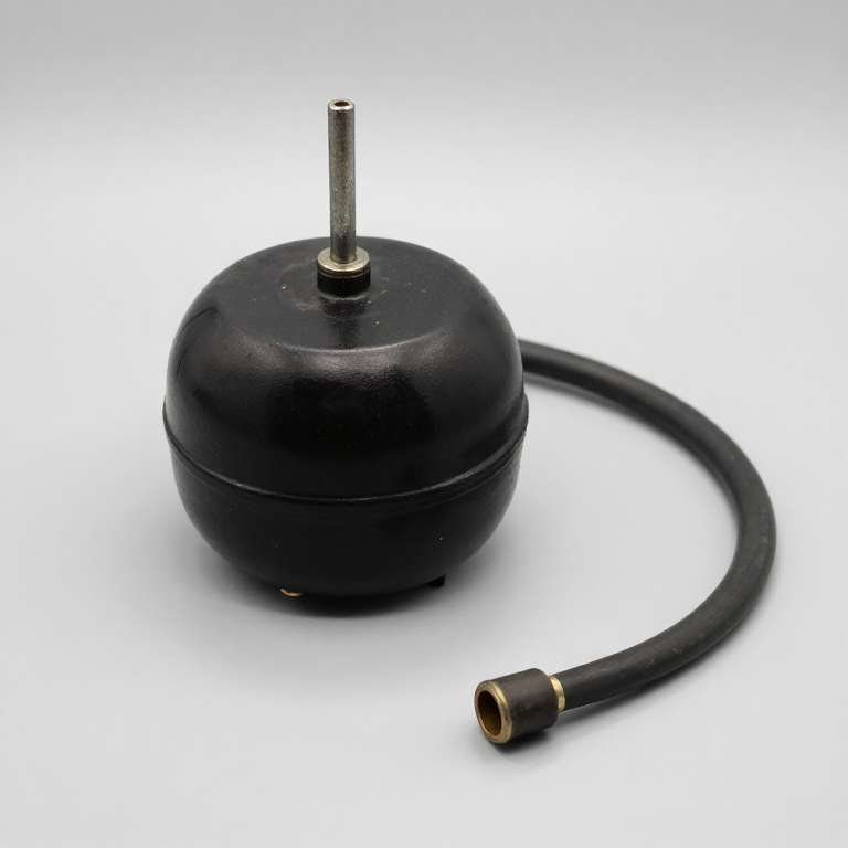


Cruise Control - Teetor's Speedostat
Ralph Teetor was blinded in an accident at the age of five and became an engineer anyway, running Perfect Circle in Indiana. The story he told about the idea is that riding with his lawyer, who slowed down whenever he was talking and sped up whenever he was listening, was making him seasick. He patented a speed-holding device and it reached the public as the Auto-Pilot on the 1958 Chrysler Imperial.
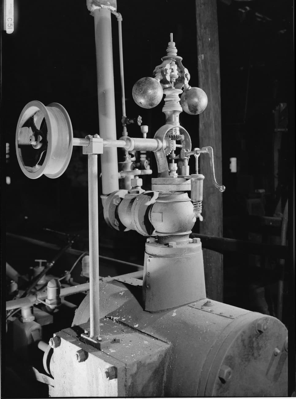
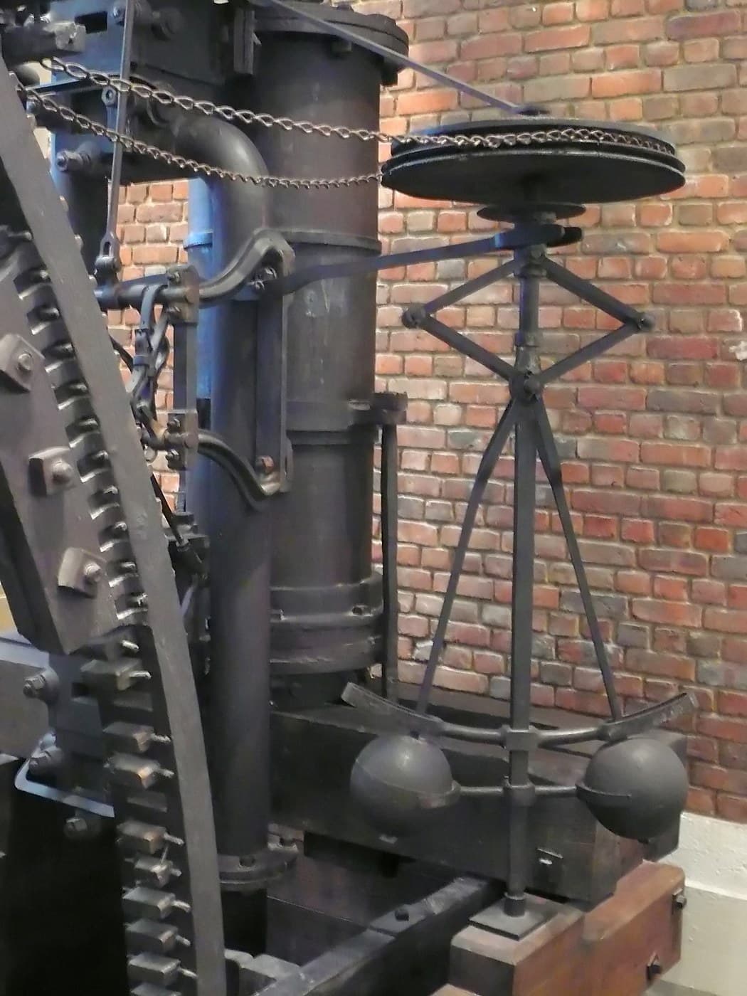
The mechanism is a governor in the direct line of the 1788 flyball: the speedometer cable spins a magnet, its drag against a spring gives a position proportional to road speed, and that position lets manifold vacuum pull on the throttle linkage. No electronics anywhere.
It is also the first loop in this batch whose entire job is rejecting a disturbance. Nothing asks the car to change speed - the setpoint sits still for an hour - and everything the controller does is answering the road. A four per cent grade, which is an ordinary motorway hill, more than doubles the force a 1500 kg car needs at 100 km/h, and it arrives without warning.
That is why a proportional controller alone cannot do this job. It only produces extra throttle by being wrong, so on a hill it settles several kilometres an hour slow, and the gain that would fix that is past the point where the driveline lag turns the loop into a surging oscillator. The throttle has to end up somewhere new while the speed ends up exactly where it started, and only an integrator can hold an output with no input left to sustain it - Maxwell's distinction between a moderator and a governor, arriving in a car ninety years later.
The reason it is fitted is not comfort. A driver whose speed wanders a few kilometres an hour burns a couple of per cent more fuel, which across a fleet of lorries is the whole business case.
Fortgeschritten
4 hours
Anweisungen
1
1
A motor, a slotted disc and a thumb
A motor, a slotted disc and a thumb
Cut a 60 mm disc with twenty slots around its rim, fit it to the geared motor's shaft and straddle the rim with the optical detector.
Mount a lever with a rubber pad where you can press it against the disc's edge. That lever is the hill, and being able to apply a disturbance ON PURPOSE, repeatably, is what makes the next step an experiment rather than a demonstration.
Materialien für diesen Schritt:
 Sperrholzplatte1 Blatt
 Gleichstrom-Getriebemotor1 Stück
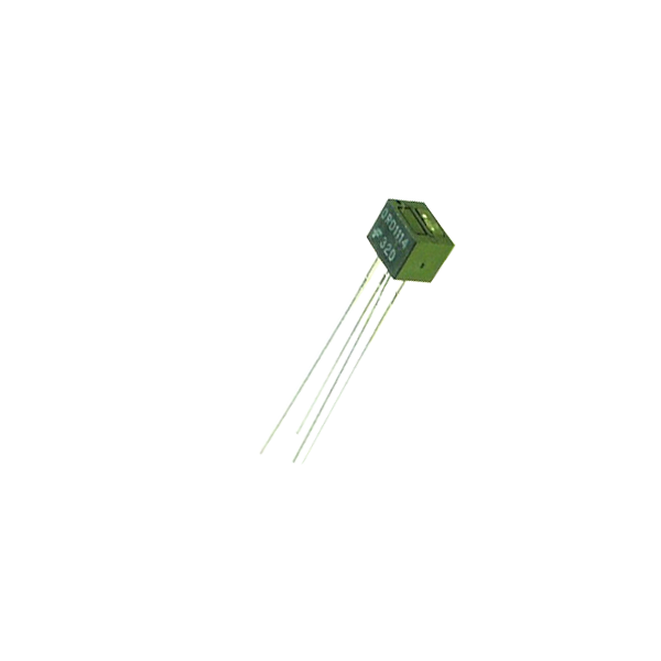 Optical Detector / Phototransistor - QRD11141 Stück
 O-Ring-Sortiment1 Set
Benötigte Werkzeuge:
 Bastelmesser
 Digitaler Messschieber 6 Zoll
 Akkubohrschrauber
 Lineal
2
2
Proportional, then proportional plus integral
Proportional, then proportional plus integral
One constant switches between a 1950s vacuum servo and what replaced it. Log the speed to the serial plotter and press the lever for five seconds at a time.
In proportional mode the speed sags while you press and stays sagging. Switch to PI and it sags, then climbs back to exactly where it was - and you can watch the integral term filling up in the fourth column as it does.
speed_regulator.inocpp
Materialien für diesen Schritt:
 N-Kanal-MOSFET IRF540N1 Packung
 Widerstandssortiment 1/4 W1 Set
 Dupont-Steckkabelsatz (Stecker-Buchse)1 Set
Benötigte Werkzeuge:
 Arduino Uno R3
 Steckbrett
 Desktop-Computer
 Labornetzgerät
3
3
The hill in newtons, the droop in km/h, and four schemes
The hill in newtons, the droop in km/h, and four schemes
Jupyter-Notebook wird geladen …
Benötigte Werkzeuge:
Desktop-Computer4
4
Compendium: what must happen when you touch the brake
Compendium: what must happen when you touch the brake
A cruise control is the first feedback loop most people meet that can hurt them, and most of the engineering is in getting OUT of the loop rather than staying in it. The brake pedal must disengage the system through a path that does not depend on the controller being healthy - on the vacuum systems a mechanical valve dumped the servo the instant the pedal moved, and modern installations still use a separate switch wired so that a failure disengages rather than engages. The clutch does the same, because a loop that keeps asking for speed with the driveline disconnected will take the engine to its limit in a couple of seconds. There is also a lower speed limit, typically around 40 km/h, and it exists because the car's own speed time constant grows as it slows and the loop's margin shrinks with it.
The awkward disturbance is the downhill one. On a four per cent descent the road supplies more force than the drag absorbs, so the throttle shuts and the car speeds up anyway - the actuator has run out of range in the direction it needs, exactly like the aileron on its stop in blueprint 2. The controller has nothing left to do and the integral will wind itself backwards unless clamped. The answer is an actuator that can take energy OUT, which is why systems that hold speed downhill are wired to the transmission or the engine brake and not only to the throttle.
Materialien
7- 1 BlattPlatzhalter
- Platzhalter
- Optical Detector / Phototransistor - QRD111410% Provision1 Stück€1.08
- 1 SetPlatzhalter
- 1 PackungPlatzhalter
- Platzhalter
- Platzhalter
Benötigte Werkzeuge
8- Platzhalter
- Platzhalter
- 1 vendor sell this, none ship to you yetPlatzhalter
- Platzhalter
- 1 vendor sell this, none ship to you yetPlatzhalter
- 1 vendor sell this, none ship to you yetPlatzhalter
- Platzhalter
- Platzhalter
Geschätzte Gesamtkosten
Was der Maker gekauft hat. Materialien ohne Preis besorgst du dort, wo du sie kaufst.
Verwandte Blueprints
Diese Blueprints teilen Wissen — Techniken, Materialien oder Prinzipien


CC0 Gemeinfrei
Dieser Blueprint ist unter CC0 veröffentlicht. Sie dürfen dieses Werk für jeden Zweck frei kopieren, ändern, verbreiten und verwenden, ohne um Erlaubnis zu fragen.
Unterstützen Sie den Maker, indem Sie Produkte über seinen Blueprint kaufen, wo er eine Maker-Provision von Anbietern festgelegt, verdient. Oder erstellen Sie eine neue Iteration dieses Blueprints und verbinden Sie ihn in Ihrem eigenen Blueprint, um Einnahmen zu teilen.