
Zusammenarbeit
KUNST
SCHÖNHEIT & WELLNESS
HANDWERK
KULTUR & GESCHICHTE
UNTERHALTUNG
UMFELD
ESSEN & GETRÄNKE
REVERSE ENGINEERING
WISSENSCHAFTEN
SPORT
TECHNOLOGIE
WEARABLES
Digital Caliper: Capacitive Scale and Slider with Two-Chip Electronics (Baxter and Buehler, Starrett, 1986)
Ed

Erstellt von

Ed

2. November 2026FI
13
0
0
0
0

Digital Caliper: Capacitive Scale and Slider with Two-Chip Electronics (Baxter and Buehler, Starrett, 1986)

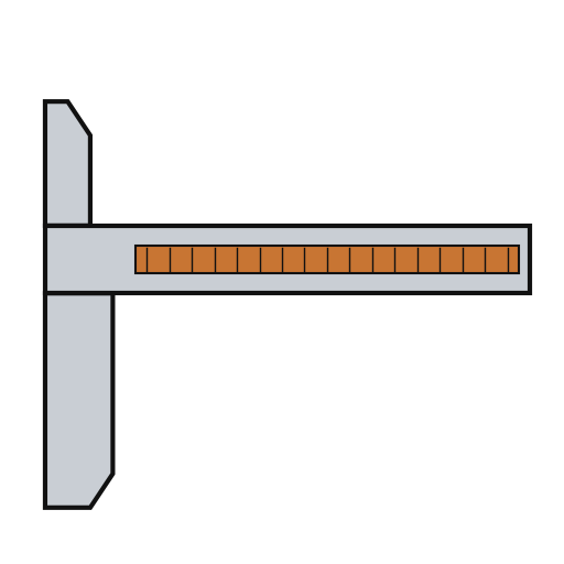
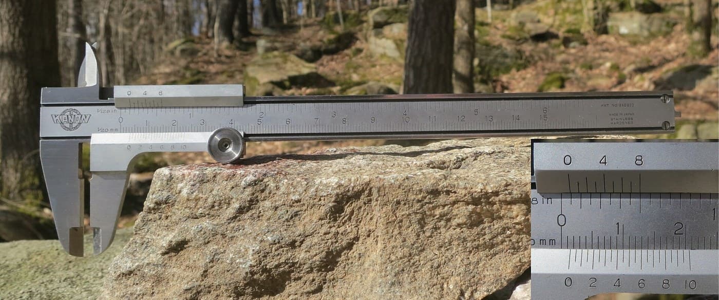
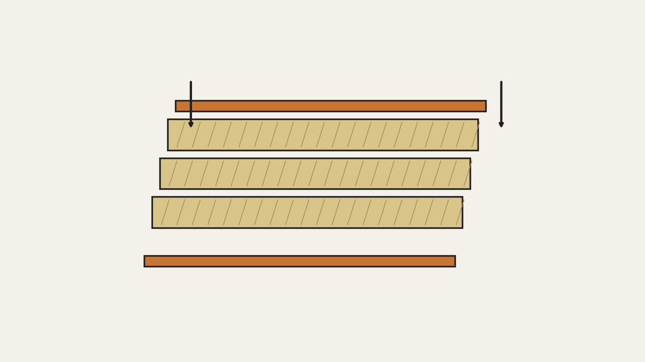
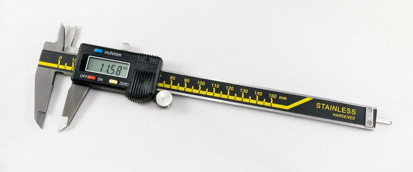
A six-inch caliper that reads out on a display. Under the slide, a strip of etched copper bars runs along the beam. Electrodes on the slider pass a signal through the bars by capacitance, and the slider's electronics count the bars crossed and work out the position in between. Result: a digital caliper reading in inches or millimetres, repeatable to a ten-thousandth of an inch, with floating zero, peak hold and high/low limits. It runs on two 1.5 V cells at 10-50 microamps. Source: L. K. Baxter and R. J. Buehler (L. S. Starrett Co.), US Patent 4,586,260 (1986). Unknown: the metal of the beam, slide and rod, their dimensions, the processor's program, and how the chips and display are made. Ours: the etchant, photoresist and glue. Picture: Wikimedia Commons.
Erfahren
2 days

Anweisungen

1

Etch the scale

Etch the scale pattern onto a strip of copper-clad epoxy fibreglass with photoresist and etchant. Each copper bar is 0.40 inch long, with a wider centre 0.12 inch long and two ends 0.14 inch long. Space the bars on 0.05 inch centres: the centres sit 0.004 inch apart, the ends 0.025 inch apart. Run the pattern the full length of the scale. Ours: dry film resist and ferric chloride.

Materialien für diesen Schritt:

Leiterplatten-Rohling (kupferkaschiert)Leiterplatten-Rohling (kupferkaschiert)1 strip, length of the beam

Benötigte Werkzeuge:

Trockenfilm-FotoresistTrockenfilm-Fotoresist
Eisen(III)-chlorid-LösungEisen(III)-chlorid-Lösung
Chemikalienbeständige HandschuheChemikalienbeständige Handschuhe
2

Fix the scale into the beam

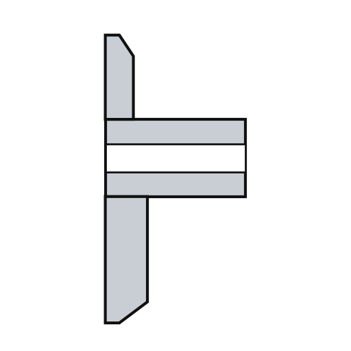
The beam is a metal bar with the fixed outside and inside jaws at one end, a wide shallow channel in its face and a second channel along its back. Fix the scale permanently into the face channel, copper up. The patent allows etching before or after this step. Not given: the metal, the dimensions and how the scale is fixed. Ours: epoxy.

Materialien für diesen Schritt:

MessschieberschieneMessschieberschiene1 with integral jaws
ZweikomponentenepoxidZweikomponentenepoxid1 a little

Benötigte Werkzeuge:
Unbekannte MaßeUnbekannte Maße
3

Fit the parts to the circuit

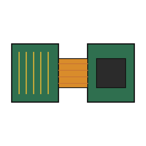
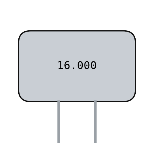
The circuit is one folded piece: a double-sided slider board joined by a flexible hinge to a circuit board. Its bottom face has two pickup electrodes, 0.750 x 0.110 inch and 0.0625 inch apart. On each side of them is an interdigitated transmitter array: fingers 0.115 inch long on 0.025 inch spacing, opening to 0.0375 inch at the centre. On the circuit board, solder or wire-bond the two chips: an NEC uPD7503 3 V processor (768 bits RAM, 2 kB ROM) and a CMOS gate array. Then fit the LCD, the 100 kHz crystal, the integrating capacitor and the MODE and SET buttons. Not given: the processor's program. Ours: a capacitor from a kit.

Materialien für diesen Schritt:

Starrflex-LeiterplatteStarrflex-Leiterplatte1 slider board + circuit board
Integrierter SchaltkreisIntegrierter Schaltkreis2 uPD7503 CPU, CMOS gate array
Segment-LCDSegment-LCD1 5 digits
SchwingquarzSchwingquarz1 100 kHz
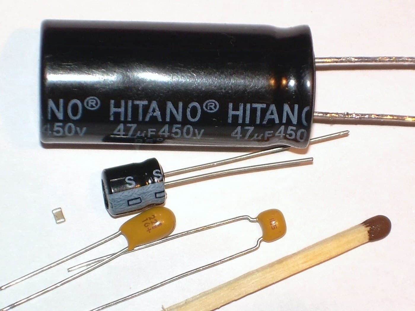
KondensatorsortimentKondensatorsortiment1 one integrating capacitor

DrucktasterDrucktaster2 MODE, SET
LötdrahtLötdraht1 a little

Benötigte Werkzeuge:

LötkolbenLötkolben
4

Build the slide

The slide frame wraps the back and edges of the beam and carries the movable jaws. Fix it to the depth rod, which runs in the back channel of the beam; the rod's free end is the depth gauge. Put the moulded plastic housing between the frame ends. Fasten two metal wear strips under the slider board, one on each side of the scale. They ride on the beam and connect the board's copper to it. Not given: the metal and sizes.

Materialien für diesen Schritt:

SchieberrahmenSchieberrahmen1 with jaws
Unbekanntes MetallUnbekanntes Metall1 depth rod and two wear strips

SchiebergehäuseSchiebergehäuse1 Stück

Benötigte Werkzeuge:

Unbekannte MaßeUnbekannte Maße

Feinschraubendreher-SatzFeinschraubendreher-Satz
5

Assemble and check

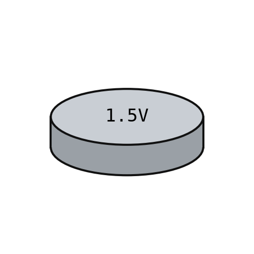
Fold the circuit into the housing recess, slider board facing the scale, and screw it to the frame. The electrodes must lie parallel to the scale bars at every point of travel. Put the two 1.5 V cells (the patent says 'zinc oxide') in the battery pockets of the circuit. The display shows five digits, a ten-thousandths bar graph, a minus sign and 'mm', plus PEAK, LOW, HIGH and LIMIT. Ours: check the reading against a vernier caliper.

Materialien für diesen Schritt:

MaschinenschraubenMaschinenschrauben2 Stück
Knopfzelle 1,5 VKnopfzelle 1,5 V2 Stück

Benötigte Werkzeuge:

Feinschraubendreher-SatzFeinschraubendreher-Satz
MessschieberMessschieber

Materialien

15

Benötigte Werkzeuge

7

CC0 Gemeinfrei

Dieser Blueprint ist unter CC0 veröffentlicht. Sie dürfen dieses Werk für jeden Zweck frei kopieren, ändern, verbreiten und verwenden, ohne um Erlaubnis zu fragen.

Unterstützen Sie den Maker, indem Sie Produkte über seinen Blueprint kaufen, wo er eine Maker-Provision von Anbietern festgelegt, verdient. Oder erstellen Sie eine neue Iteration dieses Blueprints und verbinden Sie ihn in Ihrem eigenen Blueprint, um Einnahmen zu teilen.

Diskussion

(0)

Anmelden um an der Diskussion teilzunehmen

Kommentare werden geladen...