Zusammenarbeit
KUNST
SCHÖNHEIT & WELLNESS
HANDWERK
KULTUR & GESCHICHTE
UNTERHALTUNG
UMFELD
ESSEN & GETRÄNKE
REVERSE ENGINEERING
WISSENSCHAFTEN
SPORT
TECHNOLOGIE
WEARABLES
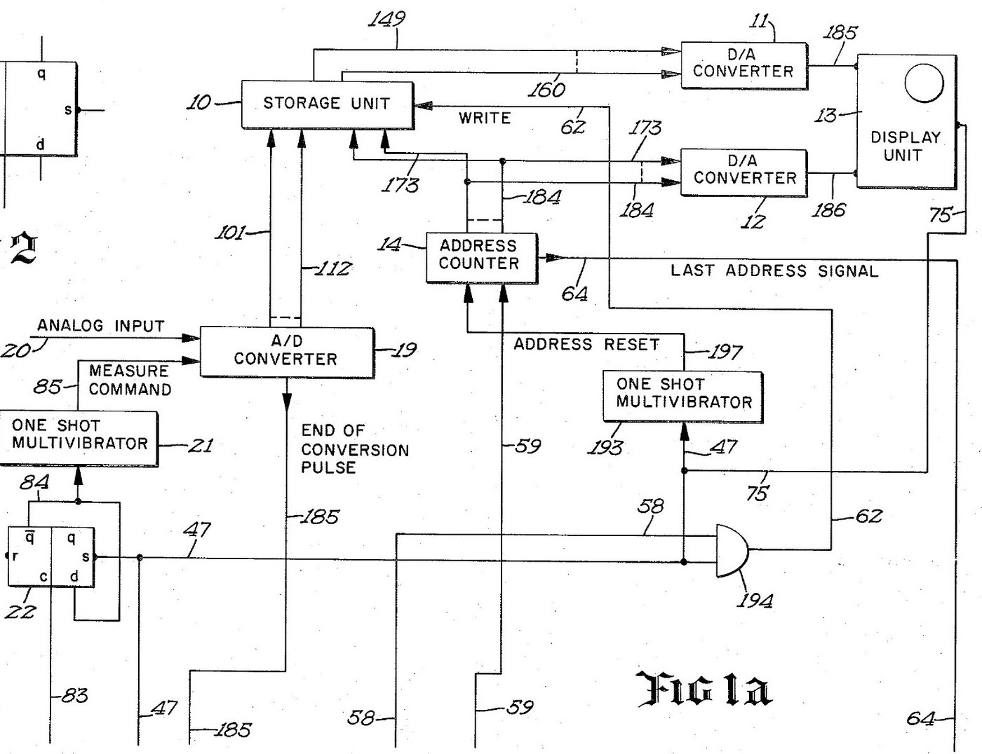


Digital Oscilloscope: Waveform Stored in Memory and Shown on a CRT (Schumann, Nicolet, US 3,816,815, 1974)
An oscilloscope with a memory. After a trigger, an analog-to-digital converter measures the input at regular intervals and writes each reading into its own memory register, replacing the old one. The screen then shows the memory: each register's number sets the beam's height, its address sets the beam's place across. The last waveform can be held on the screen as long as you like.
Result: a digital storage oscilloscope with 4,096 points of 12 bits, refresh and hold modes and single-shot capture.
Source: R. W. Schumann (Nicolet), US 3,816,815 (1974). Unknown: sample rate, bandwidth, voltages and the parts used. Picture: the patent drawing.
Experte
Unknown
Anweisungen
1
1
Sample and convert the input
Sample and convert the input
Bring the analog input to an analog-to-digital converter, through a BNC socket. A sampling oscillator, divided by four by two flip-flops so the first reading comes soon after the sweep starts, fires a one-shot multivibrator that gives the converter its measure command. The converter holds each 12-bit result on its output lines and signals the end of each conversion. Ours: a BNC socket. Not given: the sample rate.
Materialien für diesen Schritt:
 Analog-Digital-Wandler1 12-bit converter
 Taktoszillator1 sampling oscillator
 Logik-IC-Sortiment1 flip-flops, one-shots, gates
 Koaxialstecker-Satz (BNC / SO-239)1 input socket
Benötigte Werkzeuge:
 Lötkolben
 Abisolierzange
2
2
Store each reading in memory
Store each reading in memory
Wire an integrated-circuit memory of 4,096 registers, 12 bits each, that can be read without changing it. A 12-bit address counter picks the register. On each write command the register at the current address takes the last reading from the converter, and the counter steps on. When the sweep starts, a one-shot resets the counter to zero. When it reaches the last address, its last-address signal ends the sweep.
Materialien für diesen Schritt:
 Halbleiterspeicher1 4,096 x 12-bit store
Benötigte Werkzeuge:
LötkolbenAbisolierzange3
3
Drive the CRT from the memory
Drive the CRT from the memory
Feed the addressed register's number to one digital-to-analog converter and the address to a second. Their outputs drive the vertical and horizontal deflection plates of a cathode-ray tube, so the beam always stands at the height of the stored reading and at the place of its address. Wire the sweep line to the tube's intensifier, to brighten the trace while a waveform is being taken.
Materialien für diesen Schritt:
 Digital-Analog-Umsetzer2 vertical and horizontal
 Kathodenstrahlröhre1 display tube
Benötigte Werkzeuge:
LötkolbenAbisolierzange4
4
Wire the trigger and the modes
Wire the trigger and the modes
A trigger input, usually from the leading edge of the input waveform, starts the sweep, once a measure flip-flop has armed it. Put a two-position mode switch on the face: MODE I and MODE II. Add a push button in the probe, a switch on the panel and an external initiate input; each goes through a flip-flop that removes contact bounce. Two more oscillators step the memory round to refresh the display between waveforms. Mount it all in a case with its supply. Ours: toggle switches, an aluminium case, a DC supply. Not given: the supply voltages.
Materialien für diesen Schritt:
Taktoszillator2 display sequencing oscillators Kippschalter2 mode and panel switches
 Drucktaster1 probe switch
 Aluminiumgehäuse1 case
Benötigte Werkzeuge:
 Gleichstromnetzgerät
 StandbohrmaschineLötkolben
5
5
Capture and hold a waveform
Capture and hold a waveform
In MODE I, refresh: each new triggered waveform replaces the last on the screen. Press the probe or panel switch to hold: new waveforms are rejected and the last one stays on the screen. In MODE II the screen normally holds; on command, it takes the first waveform after the command, stores it and shows it steadily. Test it with a known signal.
Benötigte Werkzeuge:
 Funktionsgenerator
Materialien
10- 1 12-bit converterPlatzhalter
- 2 display sequencing oscillatorsPlatzhalter
- 1 flip-flops, one-shots, gatesPlatzhalter
- 1 input socketPlatzhalter
- 1 4,096 x 12-bit storePlatzhalter
- 2 vertical and horizontalPlatzhalter
- 1 display tubePlatzhalter
- Platzhalter
- Platzhalter
- 1 casePlatzhalter
Dieser Bauplan stellt her

Verwandte Blueprints
Diese Blueprints teilen Wissen — Techniken, Materialien oder Prinzipien
CC0 Gemeinfrei
Dieser Blueprint ist unter CC0 veröffentlicht. Sie dürfen dieses Werk für jeden Zweck frei kopieren, ändern, verbreiten und verwenden, ohne um Erlaubnis zu fragen.
Unterstützen Sie den Maker, indem Sie Produkte über seinen Blueprint kaufen, wo er eine Maker-Provision von Anbietern festgelegt, verdient. Oder erstellen Sie eine neue Iteration dieses Blueprints und verbinden Sie ihn in Ihrem eigenen Blueprint, um Einnahmen zu teilen.